EX4 Series
Table of Contents
System Mode
EO18-33027
Periodic Maintenance Procedure
11-1
Rfid Analyze Tool
EO18-33027
Unpacking
Procedure
Open
Printer Installation
Maintenance
Printer Block Screw
OPENING/CLOSING the TOP Cover
Removing the Side Panel L
OPENING/CLOSING the Printer Block
Raise the print head block until it stops
Hooks
Removing the Operation Panel
Operation Panel Ass’y Operation Panel Harness
Installation Procedure for Optional Equipment
Hooker
Disc Cutter B-EX204-QM-R
Main PC Board CN15 Disc cutter PC Board Cutter Harness
Rotary Cutter B-EX204-R-QM-R
Description ’ty/Unit Cutter Unit
Disassemble the frame into 3 parts
SMW-4x8 Determine the position by fitting the two parts here
Do not
4x8 Screw
Harness Ass’y CN7 9 pins
CN15 9 pins
Cutter Unit SM-4 x 8 Screw Notch
Installation Procedure for Optional Equipment
Peel OFF Module B-EX904-H-QM-R
Hook
Turn the power off and disconnect the power cord
Installation Procedure for Optional Equipment
CN4
Selection Switch
TBD
Bush Cut Strip Sensor Harness
Adjustment
Ribbon Saving Module B-EX904-R-QM-R
Plunger Head Up Arm Spacer Solenoid SM-4x8 Screw Frame
CN2
Installation Procedure
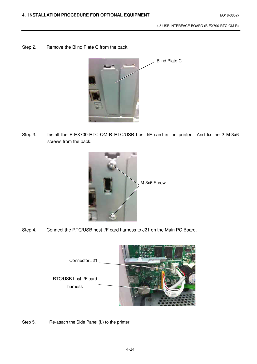
RTC/USB Host I/F Card B-EX700-RTC-QM-R
RTC/USB host I/F card 1 pc
Remove the Blind Plate C from the back
Packing List
Expansion I/O Interface Board B-EX700-IO-QM-R
Remove the Blind Plate D from the back
Installation Procedure for Optional Equipment
Wireless LAN Board B-EX700-WLAN-QM-R
Installation Procedure
Installation Procedure for Optional Equipment
Parallel Interface card B-EX700-CEN-QM-R
Remove the Blind Plate a from the back
Re-attach the Side Panel L to the printer
Operation Panel
System Mode
Overview
SELF-DIAGNOSTIC Test
DIAG. menu item list
Menu Item
Menu operation procedure example
Counter Paramete Print Contents
CUT
FEED1 ~ FEED4
Print
PRINT1 ~ PRINT4
Adjust
Parameter Settings
LATIN9
EX.I/O Mode
Reflect
Font
Maxi Code Spec
Command
Power Save Time
LBL/RBN END
RS-232C
Panel
Storage Area
USB
LAN/WLAN
Centro
Socket Port
Wlan Mode
AES Tkip WPA Mode
Default KEY
Rfid
RTC
Auto Diagnostics/AUTO Diagnostics
Print condition
Program B-EX4T1-G
Kanji None :0000
Sdram 32MB
Eeprom 256B
Head Rank
SENSOR2
Expansion I/O check contents
Internal serial I/F check contents EX.232C NG
EXP.I/O NG
EU, SX704-RFID-U2-R
SX704-RFID-U2-US-R
US, AU, TW
US, AU, KR2, TW SX704-RFID-U2-EU-R
USB Memory NG
Basic M None
Basic S None
Head broken dot check/HEAD Check
1Printer setting / Printer SET
Parameter Setting
„ Outline of Parameter Setting
LCD Display Setting / Panel
Standby action / FW/BK ACT
Setting for forward feed standby / Forward Wait
Media loading / Media Load
Forward feed standby position / Forward Wait POS
Standard speed/ STD 3ips Low speed / LOW 2ips
Ribbon save / RBN Save
Pre peel-off / PRE Peel OFF
Back feed / Back Speed
Soft control setting / Software SET
Menu list Soft control setting / Software SET
ESC LF NUL / Manual
・ ESC, LF, NUL / ESC,LF,NUL
Character code / Font Code
・ LATIN9
Control code / Code
Feed Key Function
Manual selection / Manual
・ CODE1 ・ CODE2 ・ CODE3
Peel-off wait status / Peel OFF Status
WEB Printer / WEB Printer
Character
Euro code / Euro Code
Auto head broken check / Auto HD CHK
TYPE1:
External I/O mode / EX.I/O
Ribbon near end / RBN Near END
Paper / ribbon end / LBL/RBN END
2.16 XML
MaxiCode specification / Maxi Code
・ Disable / OFF ・ Standard / STD ・ Oracle / Oracle
Compatible with the current version
Power save time / PW Save Time
Threshold selection / Threshold Select
Print method / Energy Type
Print page / Print
LCD Language
Language of LCD display / LCD Language
Machine name / Machine Name
Digit Hex Non Decimal
Contrast adjustment / Contrast
Password setting / Password
Menu list of Password setting / Password
System Mode
„ Outline of Printer Parameter Fine Adjustment
Fine adjustment value setting/ Adjust SET
Digit 50.0
Feed / Feed ADJ
Max Min Step Display Sign Integer Decimal Fullfil
Cut position / CUT ADJ
+3.0mm Cut position Paper feed direction
Cut position Head position
(b)Operation example Issue count 2, Cut interval =
System Mode
Strip position fine adjustment 0mm +3.0mm
Back feed / Back ADJ
Digit Decimal Exist Non Step
Direction position / X Adjust
Digit 99.5 Decimal Exist Non
Density fine tune Thermal transfer / Tone ADJ.TRANS
Ribbon Rewinder / RBN ADJ.FW
Ribbon Feeder / RBN ADJ.BK
Exist Non Step
Transmissive sensor fine tune / Threshold Trans
Refrective sensor fine tune / Threshold Refl
+10step
EX4T1-G EX4T1-T Speed
It sets printing condition of printer for test print
Print condition setting / Print Condition
Issue count / Issue Count
Test Print
Print method / Print Type
Issue type / Issue Type
Print speed / Print Speed
Sensor / Sensor
Type
Issue Count
Print Speed
Sensor
3 3-dot slant line print / Slant LINE3DOT
2 1-dot slant line print / Slant LINE1DOT
Character print / Characters Barcode print / Barcode
Auto print Transmissive / Auto Print Trans
Factory test / Factory Test
Auto print Reflective / Auto Print Refl
Reflective sensor / Reflect
Sensor Adjustment
„ Outline of the Sensor Adjustment
Temperature sensor/ Temperature
Transmissive / Trans
Paper empty level / PE REFL./TRANS
Ribbon end / Ribbon
This is a selection to prevent wrong user operation
RAM Clear
„ Outline of RAM Clear
No RAM clear / no RAM Clear
MODE1 HU CUT/RWD
TYPE1 XML STD
USB Status
Ribbon Back tension
Parameter setting/Password setting
Print density Direct Thermal
Ribbon Rewind
XON+READY Auto
Auto Snmp
INFRA/OPEN Wepoff
None Even
ACK/BYSY TYPE1
User mode Auto paper measurement Function Enable/Disable
RTC setting
Network / Network Menu list of Network / Network Menu Item
IP Address Setting
Wire/Wireless LAN selection / LAN/WLAN
USB
Standard
Network setting / Setting
Wlan Power Save Wins
Information
Socket port / Socket Port
Basic information / Basic Information
Gateway / Gateway Address
Subnet mask / Subnet Mask
Wireless LAN standard / Wlan Standard
Wireless LAN connection mode / Wlan Mode
・ 11b/g ・ 11g
1.3.14 802.11b transfer rate / 802.11b Baud
WEP default Key / Default KEY
Wlan power save / Wlan Power Save
1.3.13 802.11b channel / 802.11b Channel
2 USB
Wins
Wins Address / Wins Address
1.3.20 LPR
Stop bit / Stop BIT
3 RS-232C
Baud rate / Speed
Data length / Data Length
Input prime / Input Prime
Centronics / Centro
4.1 ACK/BUSY
・ TYPE1 ・ TYPE2
„ Outline of Basic Setting
Basic Setting
„ Outline of the Rfid Module Setting
Rfid Module Setting
ID Read / ID Read
Test / Test
SX704-RFID-U2-CN-R
SX704-RFID-U2 TAG ID
Module / Module
Module type / Module Type
11.2.3Tag type / TAG
Country / Country
・ 2CH ・ 3CH ・ 4CH ・ 5CH ・ 6CH ・ 7CH ・ 8CH
11.3.1Position adjustment for re-issue / ADJ Retry Position
RF channel / RF Channel
・ Auto
11.3.2Issue retry label / Issue Retry Lables
Digit 255 Decimal Non
11.3.3Read retry / Read Retry
SX704-RFID-U2-EU-R/US-R /CN-R
UHF setting / UHF Setting
11.4.1Output level / Power Level
11.3.4Write retry / Write Retry
11.4.3AGC threshold / AGC Threshold
11.4.2Q value / Q Value
11.4.4Write AGC threshold / Write AGC Threshold
11.4.5Write retry minimum AGC / Write Retry MIN AGC
Write data if access pass word matches to password setting
11.5.1Tag test setting / TAG Check
Onaccess
Password
11.5.2Multi word write / Mult Write
11.5.3Carrier sense / Carrier Sense
LCD Display example English
„ Key function
For the following, refer to the parameter setting section
Cut issue mode when the disk cutter is used
„ LED function
Down
„ Error messages
Cancel
Enter
No Ribbon
Symbols in the message
„ LCD message and LED indication
OFF Blinking
Head Error
Dhcp Client
(Ex ) ESCPC0010A00,0300,2,2,A,00,BLFNUL
LCD Display
(Ex ) ESCT20G30LFNUL
Move to 3. Paper
Threshold Setting
Threshold Setting Operation Example (English)
Depressing Pause
Sensor type Judgement
Judgment display
On Line Mode
Online Mode LCD Display Example (English)
Online Mode LCD Display
Icon
Online Mode Display TRANSITION, Operation example (English)
Help message for paper empty *1
Help Display
Help Display TRANSITION, Operation EXAMPLE(English)
Online mode Error content
Periodic Maintenance Procedure
Remove paper debris or label glue from the media path
50 km
When the Strip Module is used
Troubleshooting
Troubleshooting
System Requirement
Rfid Analyze Tool
Set up
Setup Disk Installation Setup Disk consists of one CD-ROM
V1.5
Main Menu
Application Functions
File Menu
EO18-33027
End Exit Exits from the Analyze Tool program
Tool Menu
NON, XON, XON/XOFF
Test Option
Sheet Setting Makes settings for the media to be used
Select the printer model
Select the test mode This menu is not available
Displays Printer Version and Rfid Module Version
Example
Operating Procedure
Click on the Tool menu, and choose CommSetting
RTS/CTS+XON/XOFF
Rfid Analyze Tool
Tag Data
Rfid Analyze Tool
Write/Read Results Box When U2 is selected
Write/Read Results Box