AIR-CONDITIONER
Contents
10-1 Summary of Troubleshooting 10-2
Outdoor Controls Outdoor Print Circuit Board
11-1 Indoort Unit Slim Duct Type 107
14-1 Indoor Unit 142 14-2 Outdoor Unit 147
Explanation of indications
Explanation of illustrated marks
Confirmation of warning label on the main unit
Indication Explanation
∗ For details, refer to the parts list
Never recover the refrigerant into the outdoor unit
Catch the inner wires
Do not modify the products
For a check, turn off the power breaker
Before test run, install the front panel and cabinet
Check the following items after reinstallation
Metal section Earth position
Safety Caution Concerned to New Refrigerant
Pipe Materials
Copper pipe Piping
Flare nut
General tools Conventional tools can be used
R410A Conventional air
Used tool Usage
Way Air Discharge Cassette Type
Single type
Indoor unit
Outdoor unit
Concealed Duct Type Single type
TCB-AX21E2
Under Ceiling Type Single type
TCB-AX21E2, AX22CE2
High Wall Type Single type
402MUT-E 452MUT-E 562MUT-E Outdoor unit
404ATZZG-E 454ATZZG-E 564ATZZG-E
Twin type
Slim Duct Type Single type
404SDT-E 454SDT-E 564SDT-E Outdoor unit
RAV-SM404SDT-E
Super Digital Inverter
Model name Outdoor unit
404ATZZG-E 454ATZZG-E 564ATZZG-E 804ATZZG-E
Operation characteristic curve Super Digital Inverter
Cooling Heating
Current a
Compressor speed rps Current a
Capacity variation ratio according to temperature
Cooling Heating SP45
SP40
Ratio Capacity
Air filter
Refrigerant piping
Drain-up port Hung-up plate
Space required for service
RAV-SP404ATZZG-E, RAV-SP454ATZZG-E, RAV-SP564ATZZG-E
Power supply inlet hole Kockout hole
Name
RAV-TWP30E2, RAV-TWP50E2 Simultaneous Twin
Model RBC
Dimension table
Capillary tube specifications
Single type Combination of 1 indoor unit and 1 outdoor unit
Twin type Combination of 2 indoor units and 1 outdoor unit
CAM-B30YGTF-2
Outer dia. ØA
PMV
CAM-B30YGTF-2
RAV-SM404SDT-E, RAV-SM454SDT-E
Control P.C. Board
For Indoor Unit
MCC-1570
Slim Duct Type
Board
MCC-5009
Color
Identification
MCC-1571
Specifications of Electrical Parts
Parts name Type Specifications
Safety During Installation/Servicing
Piping Materials and Joints Used
Processing of Piping Materials
1 Thicknesses of annealed copper pipes Thickness mm
Outer diameter mm R410A R22
Minimum thicknesses of socket joints
Flare and flare nut dimensions for R410A
Flare and flare nut dimensions for R22
R410A R22 R410A, R22 Clutch type Wing nut type
Diameter
Nm kgfm
Wrenches available on the market
Required Tools
Refer to the 4. Tools
Low temperature brazing filler
Flux Reason why flux is necessary
Materials for Brazing Silver brazing filler
Phosphor bronze brazing filler
Characteristics required for flux
Types of flux
Piping materials for brazing and used brazing filler/flux
Brazing
Basic Conditions Needed to Reuse the Existing Pipe
Branching Pipe for Simultaneous Operation System
Curing of Pipes
Restricted Items to Use the Existing Pipes
Existing pipe no * Use a new pipes
SW802 When shipped from factory When using existing pipe
Handling of Existing Pipe
Reference outside diameter Wall thickness
Indoor Controller Block Diagram
Connection of Wired Remote Controller
Connection of Wireless Remote Controller Kit
Indoor unit #1 Master Wireless remote controller kit
Max units
Outline of specifications Remarks
Ts Setup temp
Ta Room temp
To Outside temp
Setting at shipment
Setup data
+ temp. correction
Room temp. control
Tc ≥ 60C, the air speed increases by 1 step Temperature
Cool
Slim Duct Type
When Q or R is established 5 minutes after
Tcn
Conditions Tc n
Time
Setup at shipment
Control temp. C
Case of wired remote controller
Command frequency
At shipment of Item code DN CC to
Performed. Unit stops Frequency fixed
Setup temperature is shifted every 20 minutes,
Restriction ratio can be set by keeping
Connector No Pin No Specifications Remarks
Function
Indoor
Print Circuit Board
MCC-1570
Discharge temperature release control
Outdoor Controls
PMV Pulse Motor Valve control
Case of RAV-SP56 and SP80 models
Outdoor fan control
Cooling fan control SP56
SP80
Revolution frequency allocation of fan taps rpm
Coil heating control
Heating fan control
SP56
SP80
Short intermittent operation preventive control
Current release control
Temperature range SP56 SP80
Current release value shift control
Defrost control SP56 only
Start of heating operation
Normal To Abnormal To
SP80 only
Compressor protective control SP80 only
¡ Short circuit, × Open
J805 J806
Pulse Motor Valve PMV control
Case of RAV-SP40 and SP45 models
Operation with WE
Allocations of fan tap revolutions rpm
TE ˚C TD ˚C
Temp. range 34.1Hz 34.1Hz ≤ 58.6Hz 58.6Hz ≤ f Min Max
Temp. range 38.9Hz 38.9Hz ≤ f 67.6Hz 67.6Hz ≤ f
Maximum
Defrost control
Start of heating operation
Zone
Outdoor Print
Circuit Board
MCC-5009
Fan motor output
Before troubleshooting
Troubleshooting procedure
Wired remote controller type
Wireless remote controller type
Trouble Confirmation of lamp display
Troubleshooting
Outline of judgment
Lamp indication Check code
Cause of trouble occurrence
Lamp indication Check code Cause of trouble occurrence
Case thermostat worked
Others Other than Check Code
Check Code List Indoor
Remote controller detected
Indoor unit detected
Central control devices detected
Check Code List Outdoor
Way valve inverse error
Open/Short of heat exchanger TCJ was detected
Error mode detected by indoor unit
Cause of operation Status
Cause of operation
Error mode detected by outdoor unit
Series
Operation of diagnostic function
E09 error
YES
E04 error
E10 error
E18 error
E08, L03, L07, L08 error
L09 error
L20 error
L30 error
P30 error Central controller
P10 error
F10 error
P12 error
CN333 CN334
F02 error
F01 error
C06 error TCC-LINK central controller
E03 error Master indoor unit
F29 error
P31 error Follower indoor unit
LED display legend l Go off, ¡ Go on, ¥ Flash 5Hz
Case of SP40 to
Power supply error, Current detection circuit error
Discharge temp. error
Power supply error Voltage error
L29
Outdoor fan system error
Position detection circuit error
P22
P26
Latest error display
Error display, which occurs at present
Display selection
Only 1 of SW803 is on
Display Display 2 Heat exchanger temp. sensor TE error
Display Heat exchanger temp. sensor TL error →
Case of SP80
Is connection of CN603 correct?
F12 Display 1 Display 2 Suction temp. sensor TS error
F13 Display Display 2 Heat sink temp. sensor TH error
F31 Display Eeprom error
H03 Display 1 Display 2 Current detection circuit error
H02 Display Compressor lock
L10 Display
100
Check outdoor P.C. board Defect → Replace
P05 Display 1 Display 2 Power supply error
101
Is there refrigerant shortage? Recharge refrigerant
Repair defective position Replace defective part
102
P15 Display 1 Display 2 Gas leak detection
103
Exchange to cooling cycle Exchange to heating cycle
104
105
Single operation check for outdoor fan
Outdoor fan single operation
Display
Temperature Resistance value characteristic table
TA, TC, TCJ, TE, TS, to sensors
TD, TL sensors
106
Replacement procedures
107
Setting data read out from Eeprom
C. Board for indoor unit servicing replacement procedures
108
Swing operation also starts if it has the louvers
Writing the setting data to Eeprom
109
Eeprom layout diagram
110
Setting data Code No. table example
111
Type Code No Indoor unit capacity Code No
Test Run Setup on Remote Controller Wired remote controller
Practical operation
112
Function Selection Setup
LED Display on P.C. Board D501 Red
D403 Red
D503 Yellow Main bus communication
Contents
114
Function selection item No. DN list
Setup method
When connected 2 remote controllers operate an indoor unit
When connected 2 remote controllers operate the twin
Operation
Calling of sensor temperature display
Monitor Function of Remote Controller Switch
Procedure
116
Calling of error history
Contents
Group control operation
System example
Indoor unit power-ON sequence
By feed unit Automatic address judgment
Initial communication
Usual regular communication
Microprocessor block diagram
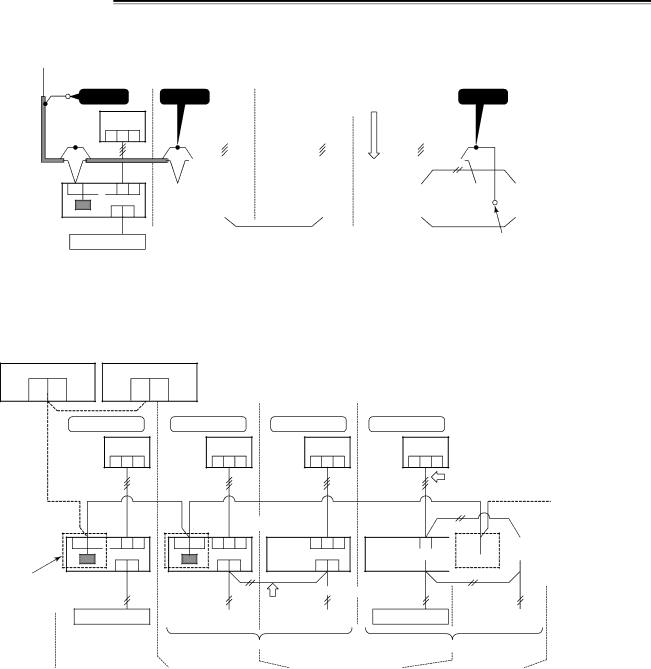
TCC-LINK wiring connection
TCC-LINK Adapter For TCC-LINK Central Control Function
119
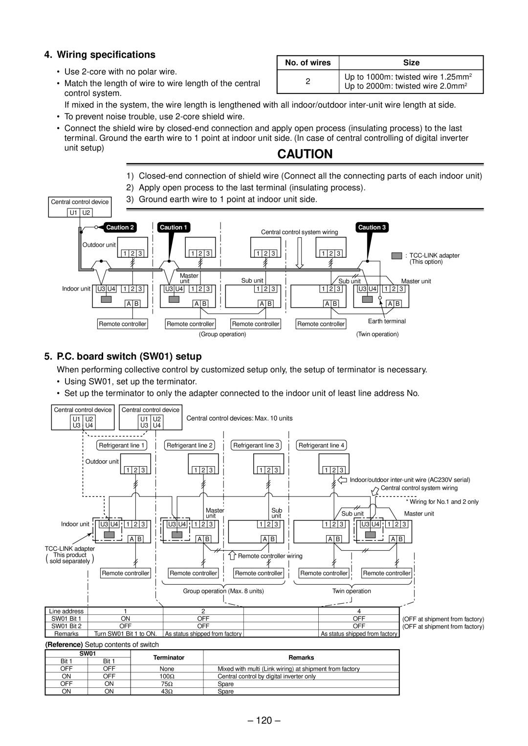
Wiring specifications
C. board switch SW01 setup
Ground earth wire to 1 point at indoor unit side
No. of wires Size
External view of P.C. board assembly
Address setup
Setup from remote controller at indoor unit side
121
How to set contents of save operation
Changing of settings of for applicable controls
When installing separately sold filters
123
Setup of external static pressure
When wireless remote controller is used
To restore the factory settings
Change on wired remote controller
How to set up power saving mode
Change of lighting time of filter sign
To secure better effect of heating
125
Refrigerant Recovery Control
Operation method
126
Function Setting position Control contents
Function Set position Control contents
127
Defrost control
∗ All LED are colorless when it goes off
Specifications Operation contents
128
Operation part
Switch Function / Contents Refer
Selection of LED display SW800, SW803 operation
129
Display selection list
Error display
Error contents
130
131
Specific operation for maintenance check SW801, SW804
Operation when pushdown button switch SW801 is pushed
132
Specific operation
SW804 Operation when pushdown button switch SW801 is pushed
133
Item code Data at shipment Setup data range
134
System Configuration
Terminology
135
Single Twin
Automatic Address Example from Unset Address No miswiring
136
Header unit
Follower unit
137
Standard One outdoor unit Single Twin Triple
Multiple groups operation
Wiring diagram
138
Single system
Address Setup Manual setting from remote controller
139
To know the position of indoor unit body by address
140
Button if the unit stops
Unit No -1is displayed on LCD
Maintenance/Check list
Part name Object Contents of check Contents of maintenance
141
No. Part name Procedure Remarks
142
Detachment
Attachment
No. Part name Procedure
143
Part name Procedure
144
Case of drain pump incorporated model
145
Fan motor 1. Detachment
146
Drain pump, 1. Detachment
Part name Procedure Remarks
147
Detachment
Attachment
No. Part name Procedure
148
149
150
Procedure Remarks
151
Tighten the flange nut with torque 4.9Nm 50kgf/cm
Part name
152
153
Pulse Motor Valve
Fan guard
With minus screwdriver along with
RAV-SP804AT-E, RAV-SP804ATZ-E, RAV-SP804ATZG-E
154
155
156
Exchange of 1. Control P.C. board
Remove the relay connector connected to
157
Exchange of 1. Reactor
Electric parts Carry out works of 1 of 1
158
Part name Procedure
159
Compressor 1. Removal of broken compressor
Control P.C. board
Compressor Using a burner, remove the discharge
160
Compressor lead Pipe and the suction pipe connected to
Compressor to the bottom plate
161
Compressor 2. Mounting of compressor
162
Vacuuming
Refrigerant charging
Forced full-opening method of PMV
163
RAV-SM404SDT-E, RAV-SM454SDT-E, RAV-SM564SDT-E
164
165
Location Description Model Name
404SDT-E 454SDT-E 564SDT-E
Parts assembly
404 403 405 402
166
RAV-SP454AT-E, RAV-SP454ATZ-E, RAV-SP454ATZG-E
167
168
Location Description Model Name RAV-SP
404ATZ-E
454ATZ-E
Inverter assembly
169
Location Description Model Name
404ARZ-E
37,38
170
171
Location Description Model Name RAV-SP
564ATZ-E
564AT-E
Inverter assembly
172
30, 31
173
174
804ATZ-E
804AT-E
175
804ATZ-E 804ATZG-E
Location
Model Name RAV-SP
Check of Concentration Limit
Toshiba Carrier Corporation