INDOOR UNIT
OUTDOOR UNIT
FILE NO. A08-007
DIGITAL INVERTER
SAFETY CAUTION
SPECIFICATIONS
FAN CHARACTERISTICS
WIRING DIAGRAM
TROUBLESHOOTING
SETUP AT LOCAL SITE AND OTHERS
ADDRESS SETUP
EXPLODED VIEWS AND PARTS LIST
SAFETY CAUTION
DANGER
Explanation of indications
Explanation of illustrated marks
Do not modify the products
metal section Earth position
1. Safety Caution Concerned to New Refrigerant
2. Cautions on Installation/Service
New Refrigerant R410A
3. Pipe Materials
4. Tools
Tools exclusive for R410A The following tools for R410A are required
General tools Conventional tools can be used
1. SPECIFICATIONS
1-1. Indoor Unit
1-1-1. 4-Way Air Discharge Cassette Type
Single type
1-1-2. Concealed Duct Type Single type
Indoor unit
RAV-SM562BT-E
RAV-SM802BT-E
1-1-3. Under Ceiling Type Single type
Indoor unit
RAV-SM562CT-E
RAV-SM802CT-E
1-1-4. High Wall Type Single type
Indoor unit
RAV-SM562KRT-E
RAV-SM802KRT-E
Indoor unit
RAV-SM
402MUT-E
452MUT-E
Twin type
Indoor unit
RAV-SM402MUT-E
Indoor unit
1-1-6. Slim Duct Type Single type
Indoor unit
RAV-SM
404SDT-E
Twin type
Indoor unit
RAV-SM404SDT-E
Indoor unit
1-2. Outdoor Unit
Super Digital Inverter
Model name
Outdoor unit
1-3. Operation Characteristic Curve
Operation characteristic curve Super Digital Inverter
RAV-SP564AT-E, RAV-SP564ATZ-E, RAV-SP564ATZG-E
RAV-SP804AT-E, RAV-SP804ATZ-E, RAV-SP804ATZG-E
Capacity variation ratio according to temperature
RAV-SP404AT-E, RAV-SP404ATZ-E, RAV-SP404ATZG-E
RAV-SP454AT-E, RAV-SP454ATZ-E, RAV-SP454ATZG-E
RAV-SP564AT-E, RAV-SP564ATZ-E, RAV-SP564ATZG-E
2. CONSTRUCTION VIEWS EXTERNAL VIEWS
2-1. Indoor Unit
RAV-SM404SDT-E, RAV-SM454SDT-E, RAV-SM564SDT-E
2-2. Outdoor Unit
Space required for service
RAV-SP404ATZZG-E, RAV-SP454ATZZG-E, RAV-SP564ATZZG-E
RAV-SP804ATZZG-E
Z views
Name
RAV-TWP30E2, RAV-TWP50E2 Simultaneous Twin
Model RBC
TWP30E2
TWP50E2
3. SYSTEMATIC REFRIGERATING CYCLE DIAGRAM
3-1. Indoor Unit
Dimension table
Capillary tube specifications
3-2. Outdoor Unit
RAV-SP404AT-E, RAV-SP404ATZ-E, RAV-SP404ATZG-E
RAV-SP454AT-E, RAV-SP454ATZ-E, RAV-SP454ATZG-E
RAV-SP404AT-E, RAV-SP404ATZ-E, RAV-SP404ATZG-E
RAV-SP564AT-E, RAV-SP564ATZ-E, RAV-SP564ATZG-E
RAV-SP564AT-E, RAV-SP564ATZ-E, RAV-SP564ATZG-E
RAV-SP804AT-E, RAV-SP804ATZ-E, RAV-SP804ATZG-E
RAV-SP804AT-E, RAV-SP804ATZ-E, RAV-SP804ATZG-E
4. FAN CHARACTERISTICS
4-1. Slim Duct Filter Attached
RAV-SM404SDT-E, RAV-SM454SDT-E
RAV-SM564SDT-E
5. WIRING DIAGRAM
5-1. Indoor Unit
Control P.C. Board
for Indoor Unit
1 2 3 L N
P.C. Board
MCC-5009
Outdoor Unit
MCC-1571
Control P.C. Board
Color
Identification
6. SPECIFICATIONS OF ELECTRICAL PARTS
6-1. Indoor Unit
6-2. Outdoor Unit Parts Ratings
RAV-SM404SDT-E, RAV-SM454SDT-E, RAV-SM564SDT-E
7-1. Safety During Installation/Servicing
7-2. Refrigerant Piping Installation
7. REFRIGERANT R410A
7-2-1. Piping Materials and Joints Used
7-2-2. Processing of Piping Materials
Table 7-2-1 Thicknesses of annealed copper pipes
Thickness mm
Outer diameter mm
Fig. 7-2-1 Flare processing dimensions
Table 7-2-3 Dimensions related to flare processing for R410A / R22
Flare and flare nut dimensions for R410A
Flare and flare nut dimensions for R22
Fig. 7-2-2 Relations between flare nut and flare seal surface
Table 7-2-6 Tightening torque of flare for R410A Reference values
Nominal
Outer diameter
7-3. Tools
7-4. Recharging of Refrigerant
Fig. 7-4-1 Configuration of refrigerant charging
7-3-1. Required Tools
7-5. Brazing of Pipes
3. Low temperature brazing filler
7-5-2. Flux 1. Reason why flux is necessary
7-5-1. Materials for Brazing 1. Silver brazing filler
2. Characteristics required for flux
3. Types of flux
4. Piping materials for brazing and used brazing filler/flux
7-5-3. Brazing
7-6. Instructions for Re-use Piping of R22 or R407C
7-6-1. Basic Conditions Needed to Reuse the Existing Pipe
7-6-3. Branching Pipe for Simultaneous Operation System
7-6-4. Curing of Pipes
Existing pipe NO * Use a new pipes NO
Cautions for using existing pipe
7-6-6. Handling of Existing Pipe
RAV-SP804AT-E
8-1. Indoor Controller Block Diagram
8. INDOOR CONTROL CIRCUIT Slim Duct Type
8-1-1. Connection of Wired Remote Controller
Wired remote controller Max. 2 units
8-1-2. Connection of Wireless Remote Controller Kit
Indoor unit #1 Master Wireless remote controller kit
Case of TCC-LINK adapter
Wireless remote controller kit
Master wired remote controller
Weekly timer
Indoor unit #1 Master
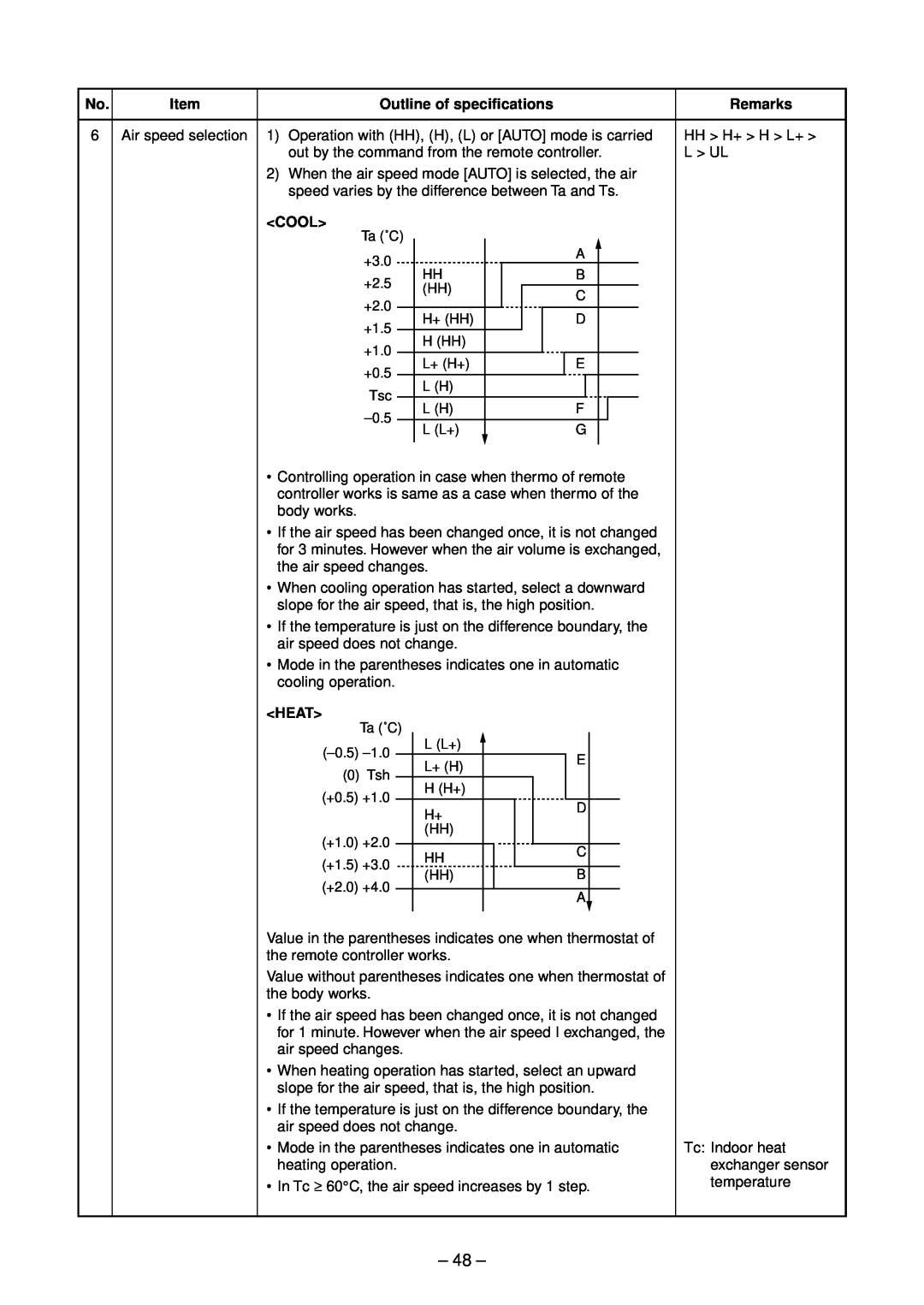
8-2. Indoor Controls Slim Duct Type
Outline of specifications
Remarks
Outline of specifications
Setup temp. correction
Remarks
limited to approximately “SB”
Outline of specifications
Remarks
COOL
Outline of specifications
Remarks
Slim Duct Type
Slim Duct Type
Outline of specifications
Tc temperature at start
Remarks
Conditions
Outline of specifications
Setup at shipment
Remarks
Outline of specifications
In case of wired remote controller
Remarks
HA control
Outline of specifications
Remarks
Outline of specifications
button Heating operation 18C setting continues
Remarks
The restriction ratio can be set by keeping
8-3. Optional Connector Specifications of Indoor P.C. Board
Connector No
Specifications
Function
8-4. Indoor
Print Circuit Board
MCC-1570
2. Discharge temperature release control
9. OUTDOOR CONTROL CIRCUIT
9-1. Outdoor Controls
1. PMV Pulse Motor Valve control
3. Outdoor fan control
3-1 Cooling fan control SP56
SP80
Revolution frequency allocation of fan taps rpm
4. Coil heating control
3-2 Heating fan control
SP56
SP80
SP56
SP80
5. Short intermittent operation preventive control
6. Current release control
7. Current release value shift control
10. Defrost control SP56 only
Start of heating operation
SP80 only
11. Compressor protective control SP80 only
Start of heating operation
1. Pulse Motor Valve PMV control
3. Current release control
2. Discharge temperature release control
REQUIREMENT
4. Outdoor fan control
Operation with WE
Allocations of fan tap revolutions rpm
5. Coil heating control
No power-ON Continuous ON L Continuous ON H
6. Defrost control
Start of heating operation
9-2. Outdoor Print
Circuit Board
MCC-5009
SP564ATZG-E
RAV-SP804AT-E, RAV-SP804ATZ-E, RAV-SP804ATZG-E MCC-1571
10. TROUBLESHOOTING
10-1. Summary of Troubleshooting
1. Before troubleshooting
2. Troubleshooting procedure
1. Before troubleshooting
2. Troubleshooting procedure
Wireless remote controller type
Trouble
10-2. Troubleshooting
10-2-1. Outline of judgment
Heat exchanger sensor TCJ error
setting of heating to cooling-only model
10-2-2. Others Other than Check Code
Disagreement of cool/heat
Cause of trouble occurrence
10-2-3. Check Code List Indoor
Remote controller detected
Indoor unit detected
Central control devices detected
Check Code List Outdoor
Page
Error mode detected by indoor unit
Operation of diagnostic function
Judgment and measures
Cause of operation
For the wireless models, an error is notified with indication lamp
Error mode detected by outdoor unit
Operation of diagnostic function
Judgment and measures
Cause of operation
after
10-2-4. Diagnostic Procedure for Each Check Code Indoor Unit
Check code E01 error
E09 error
E04 error
E10 error
Is group address setup of
Are wiring in indoor unit and
E18 error
E08, L03, L07, L08 error
L09 error
L20 error
L30 error
P30 error Central controller
P10 error
F10 error
P12 error
Does the fan rotate without trouble when handling the fan with hands?
detection signal correct? ∗
Is output of
F02 error
F01 error
C06 error TCC-LINK central controller
E03 error Master indoor unit
F29 error
P31 error Follower indoor unit
Reboot
10-2-5. Diagnostic Procedure for Each Check Code Outdoor Unit
In case of SP40 to
In case of SP40 to
→ Refer to columns H03 and P04 and then check power supply and
voltage error
Between outdoor P.C. board and terminal block
198 to
In case of SP40 to
10-2-6. Diagnostic Procedure for Each Check Code Outdoor Unit
How to check LED display on outdoor P.C. board
Dip switch setup
Latest error display
In case of SP80
Page
Is compressor under correct conditions?
Display 2 Unset model type Only when service P.C. board is used
¡ l l l
Repair defective position
Remove and improve
Open service valve fully
ventilation around the heat sink?
Power is turned on for approx. 10 seconds
In case of SP80
In case of SP80
broken pipe, abnormal overload, etc
Correct defect
Page
10-2-7. Diagnostic Procedure for Each Check Code Outdoor Unit
Temperature sensor
Temperature - Resistance value characteristic table
TA, TC, TCJ, TE, TS, TO sensors
11. REPLACEMENT OF SERVICE P.C. BOARD
Note when replacing the P.C. board for indoor unit servicing
Replacement procedures
CASE
1 Setting data read out from EEPROM
2 P.C. Board for indoor unit servicing replacement procedures
At this time, be sure to write down the setting data displayed
CODE No. required at least
3 Writing the setting data to EEPROM
Fig. 1 RBC-AMT32E
Fig. 2 EEPROM layout diagram
Table 1. Setting data CODE No. table example
Table 2. Type CODE No
Table 3. Indoor unit capacity CODE No
∗ EEPROM initial value on the P.C. board for indoor unit servicing
12. SETUP AT LOCAL SITE AND OTHERS
12-1. Indoor Unit Slim Duct Type
12-1-1. Test Run Setup on Remote Controller Wired remote controller
Using the timer time
12-1-4. Function Selection Setup
Procedure Perform setting while the air conditioner stops
Using the set temperature TEMP. buttons, specify the item code DN
Using the timer time
Contents
Function selection item No. DN list
12-1-5. Wiring and Setting of Remote Controller Control
2-remote controller control Controlled by 2 remote controllers
Wired remote controller
How to set wired remote controller as sub remote controller
n Calling of sensor temperature display
2 4 1
12-1-6. Monitor Function of Remote Controller Switch
Procedure
n Calling of error history
1 2
Contents
Procedure
n Indoor unit power-ON sequence
By feed unit Automatic address judgment
Initial communication
Usual regular communication
12-2. Setup at Local Site / Others
2. Microprocessor block diagram
3. TCC-LINK wiring connection
12-2-1. TCC-LINK Adapter For TCC-LINK Central Control 1. Function
4. Wiring specifications
5. P.C. board switch SW01 setup
12-3. How to Set up Central Control Address Number
6. External view of P.C. board assembly
7. Address setup
1. Setup from remote controller at indoor unit side
3. How to set contents of save operation
4 Push SET and then push TEST to finish the setup
1 Push UNIT LOUVER button for 4 seconds or more
Push
n Changing of settings of for applicable controls
4. When installing separately sold filters
When power is turned on for the first time after installation
When power is turned on for the second or later time
n Setup of external static pressure
1 → 2 → 3 → 4 → 5 →
When wireless remote controller is used
To restore the factory settings
n How to set up power saving mode
n Change of lighting time of filter sign
n To secure better effect of heating
1 → 2 → 3 → 4 → 5 →
12-4. Outdoor Unit
Operation method
12-4-1. Refrigerant Recovery Control
SP56
Setting position
Control contents
Control contents
SP56
12-4-3. Service Support Function LED Display, Switch Operation
SP80 only 1. Outline
Operation part
Display part
2. Selection of LED display SW800, SW803 operation
1 Display selection list
2 Error display
Error contents
Page
4 Specific operation for maintenance check SW801, SW804
Operation when pushdown button switch SW801 is pushed
Specific operation
SW804
Operation when pushdown button switch SW801 is pushed
SW804
In case of model adopting the self hold valve RAV-SP1104AT-E, RAV-SP1404AT-E, the coil develops fever. Therefore do not perform this operation as coil is connected
13. ADDRESS SETUP
13-1. Address Setup Procedure
13-2. Address Setup & Group Control
13-2-1. System Configuration
Terminology
13-2-2. Automatic Address Example from Unset Address No miswiring
Only turning on source power supply Automatic completion
Header unit
Follower unit
13-2-3. Automatic Address Example from Unset Address No miswiring
Only turning on source power supply Automatic completion
Only turning on source power supply Automatic completion
1. Standard One outdoor unit
13-3. Remote Controller Wiring
Wiring diagram
Single system
2, 5
3, 6, 9 4, 7
1 2 3 4 5 6 7 8 9 10 11 END
13-4. Address Setup Manual setting from remote controller
1 2 END
1 2 3 END
13-5. Confirmation of Indoor Unit No. Position
Procedure
Maintenance/Check list
Contents of check
Contents of maintenance
Part name
14. DETACHMENTS
14-1. Indoor Unit
14-1-1. Slim Duct Type
REQUIREMENT
1. Detachment
2. Attachment
1. Detachment
2. Attachment
1. Detachment
In case of drain pump incorporated model
2. Attachment
Detachment
NO GOOD
Drain pan assembly
7 Fan motor 1. Detachment
2. Attachment
Float switch
9 Drain pump, 1. Detachment
2. Attachment
1. Detachment
14-2. Outdoor Unit
Procedure
1. Detachment
2. Attachment
Procedure
Front cabinet For single-phase type models
3. Attachment
No. Part name
Procedure
REQUIREMENT
1. Detachment
No. Part name
Procedure
Part name
Remarks
Control P.C
Procedure
Remarks
Rear cabinet
Procedure
Remarks
Compressor
Screws 2 pcs
Procedure
1. Detachment
2. Attachment
2. Attachment
Procedure
14-2-2. RAV-SP804AT-E, RAV-SP804ATZ-E, RAV-SP804ATZG-E
1. Detachment
2. Attachment
Procedure
1. Detachment
No. Part name
Discharge port cabinet
Procedure
4 Exchange of 1. Control P.C. board
No. Part name
PMV coil, 4-way valve coil, compressor case
Procedure
Part name
Remarks
Procedure
Cautions when assembling the fan motor
Remarks
Procedure
6 Compressor 1. Removal of broken compressor
Part name
Control P.C. board
Procedure
Part name
Remarks
Procedure
6 Compressor 2. Mounting of compressor
Part name
Procedure
3. Vacuuming
4. Refrigerant charging
1. Detachment
Procedure
3. Detachment
2. Attachment
No. Part name
15. EXPLODED VIEWS AND PARTS LIST
15-1. Indoor Unit
Location
Description
Model Name
RAV-SM
E-parts assembly
405 402
Location
Description
15-2. Outdoor Unit
15-2-1. RAV-SP454AT-E, RAV-SP454ATZ-E, RAV-SP454ATZG-E
Location
Description
Model Name RAV-SP
404ATZ-E
Inverter assembly
Location
Description
Model Name
10,30,36
37,38
26,27
2298
Location
Description
Model Name RAV-SP
564ATZ-E
Inverter assembly
7034
712707708
Location
9, 10
8, 39
15-2-3. RAV-SP804AT-E, RAV-SP804ATZ-E, RAV-SP804ATZG-E
Location
Description
Model Name RAV-SP
804ATZ-E
Inverter assembly
Description
804ATZ-E
804ATZG-E
WARNINGS ON REFRIGERANT LEAKAGE
Check of Concentration Limit
TOSHIBA CARRIER CORPORATION
23-17, TAKANAWA 3 CHOME, MINATOKU, TOKYO, 108-8580, JAPAN
Copyright 2008 TOSHIBA CARRIER CORPORATION, ALL Rights Reserved