Unit Description

2.2. The Control Module

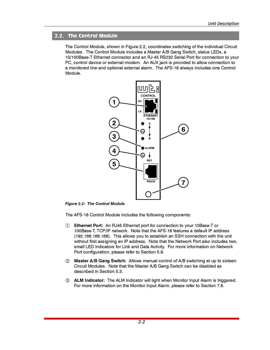
The Control Module, shown in Figure 2.2, coordinates switching of the individual Circuit Modules. The Control Module includes a Master A/B Gang Switch, status LEDs, a 10/100Base-T Ethernet connector and an RJ-45 RS232 Serial Port for connection to your PC, control device or external modem. An AUX jack is provided to allow connection to a monitored line and optional external alarm. The AFS-16 always includes one Control Module.

1

2

3

4

5

CONTROL

AC

LK

ETHERNET

10/100

A

B

ALARM

RST

RS232

6

7

Figure 2.2: The Control Module

The AFS-16 Control Module includes the following components:

Ethernet Port: An RJ45 Ethernet port for connection to your 10Base-T or 100Base-T, TCP/IP network. Note that the AFS-16 features a default IP address (192.168.168.168). This allows you to establish an SSH connection with the unit without first assigning an IP address. Note that the Network Port also includes two, small LED indicators for Link and Data Activity. For more information on Network Port configuration, please refer to Section 5.9.

Master A/B Gang Switch: Allows manual control of A/B switching at up to sixteen Circuit Modules. Note that the Master A/B Gang Switch can be disabled as described in Section 5.3.

ALM Indicator: The ALM Indicator will light when Monitor Input Alarm is triggered. For more information on the Monitor Input Alarm, please refer to Section 7.6.
2-2

Page 12
Image 12
Western Telematic AFS-16-1 manual Control Module