Unit Description
2.3. The Circuit Module
The
1 |
A
B
A
C
B
2 |
3 |
4 |
5 |
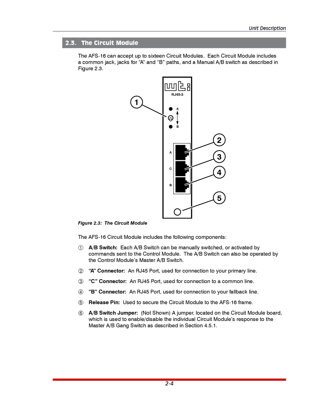
Figure 2.3: The Circuit Module
The
A/B Switch: Each A/B Switch can be manually switched, or activated by commands sent to the Control Module. The A/B Switch can also be operated by the Control Module’s Master A/B Switch.
“A” Connector: An RJ45 Port, used for connection to your primary line.
“C” Connector: An RJ45 Port, used for connection to a common line.
“B” Connector: An RJ45 Port, used for connection to your fallback line.
Release Pin: Used to secure the Circuit Module to the
A/B Switch Jumper: (Not Shown) A jumper, located on the Circuit Module board, which is used to enable/disable the individual Circuit Module’s response to the Master A/B Gang Switch as described in Section 4.5.1.