Western Telematic AFS-16-1 manual Monitor Input Level Settings, High Low

Models: AFS-16-1

1 135
Download 135 pages 23.28 Kb
Page 79
Image 79

Alarm Configuration

High Low

1 0

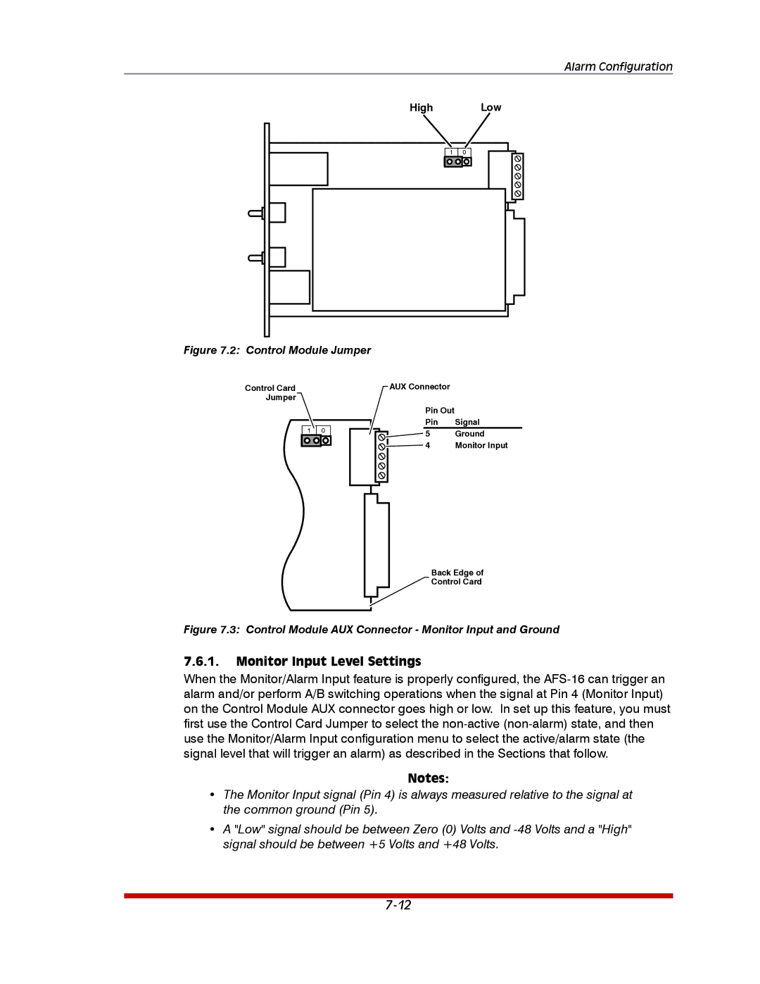
Figure 7.2: Control Module Jumper

Control Card

Jumper

1 0

AUX Connector

Pin Out

Pin

Signal

5

Ground

4

Monitor Input

Back Edge of

Control Card

Figure 7.3: Control Module AUX Connector - Monitor Input and Ground

7.6.1.Monitor Input Level Settings

When the Monitor/Alarm Input feature is properly configured, the AFS-16 can trigger an alarm and/or perform A/B switching operations when the signal at Pin 4 (Monitor Input) on the Control Module AUX connector goes high or low. In set up this feature, you must first use the Control Card Jumper to select the non-active (non-alarm) state, and then use the Monitor/Alarm Input configuration menu to select the active/alarm state (the signal level that will trigger an alarm) as described in the Sections that follow.

Notes:

The Monitor Input signal (Pin 4) is always measured relative to the signal at the common ground (Pin 5).

A "Low" signal should be between Zero (0) Volts and -48 Volts and a "High" signal should be between +5 Volts and +48 Volts.

7-12

Page 79
Image 79
Western Telematic AFS-16-1 manual Monitor Input Level Settings, High Low