Hardware Installation
Pin No.
|
|
|
|
|
|
| 1 |
|
|
|
|
|
|
| 2 |
|
|
|
|
|
|
| 3 |
|
|
|
|
|
|
| 4 |
|
|
|
|
|
|
| |
|
|
|
|
|
|
| 5 |
Pin 8 |
|
| Pin 1 | 6 | |||
|
|
|
|
|
|
| 7 |
|
|
|
|
|
|
| 8 |
| |
Pin No. Signal | |
8 | CTS |
| Pin 1 |
1 | DCD |
2 | RXD |
5 | GND |
| |
X |
|
3 | TXD |
4 | Female |
DTR | |
7 | RTS |
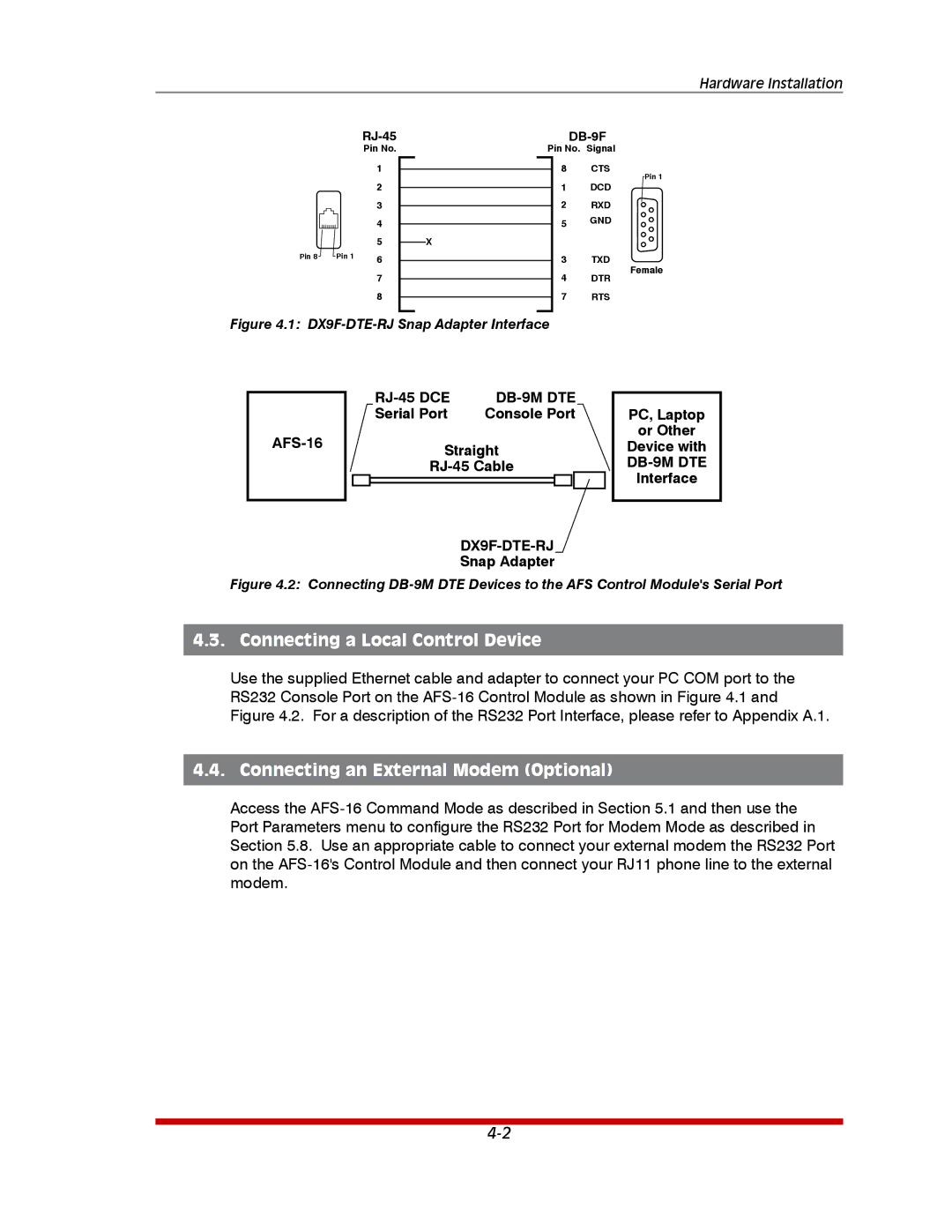
Figure 4.1: DX9F-DTE-RJ Snap Adapter Interface
Serial Port | Console Port |
Straight
Snap Adapter
PC, Laptop
or Other
Device with
Figure 4.2: Connecting DB-9M DTE Devices to the AFS Control Module's Serial Port
4.3. Connecting a Local Control Device
Use the supplied Ethernet cable and adapter to connect your PC COM port to the RS232 Console Port on the
4.4. Connecting an External Modem (Optional)
Access the