Alarm Configuration
1 0
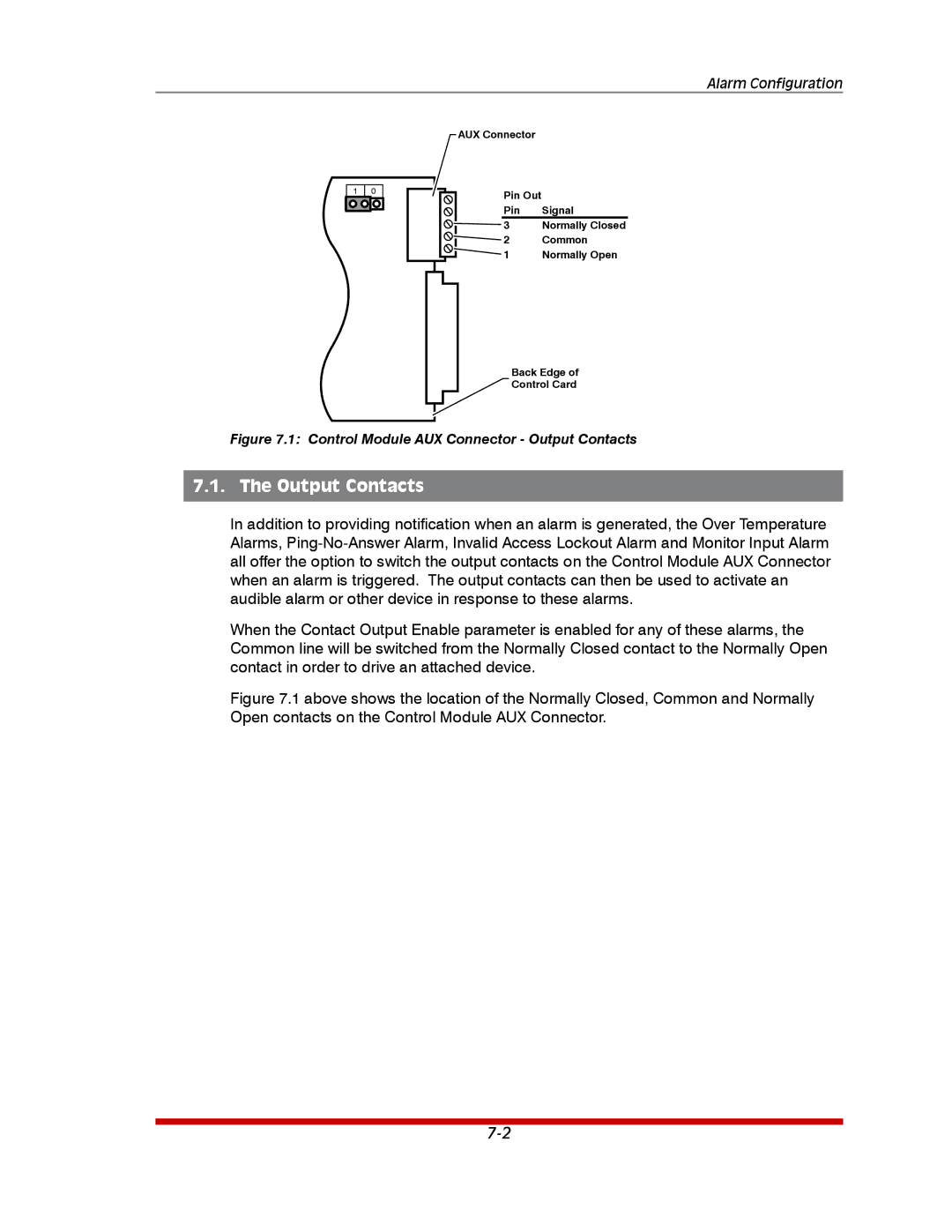
AUX Connector
Pin Out |
|
Pin | Signal |
3 | Normally Closed |
2 | Common |
1 | Normally Open |
Back Edge of
Control Card
Figure 7.1: Control Module AUX Connector - Output Contacts
7.1. The Output Contacts
In addition to providing notification when an alarm is generated, the Over Temperature Alarms,
When the Contact Output Enable parameter is enabled for any of these alarms, the Common line will be switched from the Normally Closed contact to the Normally Open contact in order to drive an attached device.