Hardware Installation
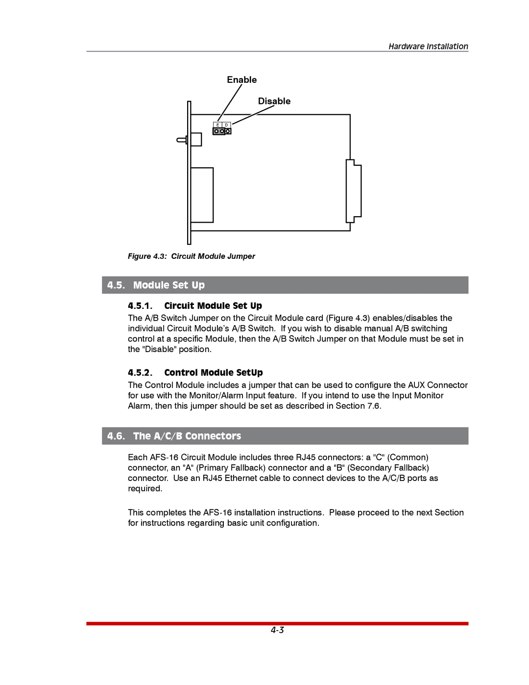
Enable
Disable
E D
Figure 4.3: Circuit Module Jumper
4.5. Module Set Up
4.5.1.Circuit Module Set Up
The A/B Switch Jumper on the Circuit Module card (Figure 4.3) enables/disables the individual Circuit Module’s A/B Switch. If you wish to disable manual A/B switching control at a specific Module, then the A/B Switch Jumper on that Module must be set in the "Disable" position.
4.5.2.Control Module SetUp
The Control Module includes a jumper that can be used to configure the AUX Connector for use with the Monitor/Alarm Input feature. If you intend to use the Input Monitor Alarm, then this jumper should be set as described in Section 7.6.
4.6. The A/C/B Connectors
Each
This completes the