Manuals
/
Xantrex Technology
/
Computer Equipment
/
Power Supply
Xantrex Technology
PV100S-208
manual
Appendix a
Models:
PV100S-208
1
113
124
124
Download
124 pages
2.86 Kb
110
111
112
113
114
115
116
117
Troubleshooting
Specifications
Physical Characteristics
Error messages
1Operating States Flow Chart
PV Ground Fault Detection
Time Delay for PV
Wiring Requirements
Warranty
Maintenance
Page 113
Image 113
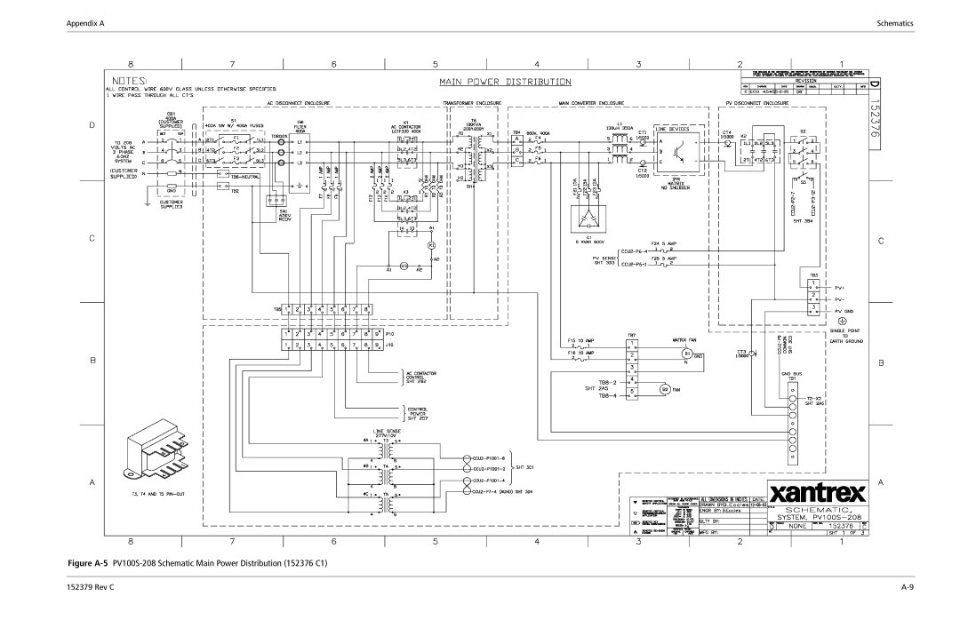
Appendix A
Schematics
Figure
A-5
PV100S-208
Schematic Main Power Distribution (152376 C1)
152379 Rev C
A-9
Page 112
Page 114
Page 113
Image 113
Page 112
Page 114
Contents
PV100S 100 kW Grid-Tied Photovoltaic Inverter
Page
PV100S 100 kW Grid-Tied Photovoltaic Inverter
Date and Revision
Scope
Purpose
Audience
Organization
Following conventions are used in this guide
Conventions Used
Related Information
Abbreviations and Acronyms
Page
Important Safety Instructions
Personal Safety
General Safety Precautions
Safety Equipment
Wiring Requirements
Safety
Lockout and Tag
Operational Safety Procedures
To isolate the PV100S
De-Energize/Isolation Procedure
Interconnection Standards Compliance
Xii
Contents
Operation
Commissioning
Troubleshooting
Preventative Maintenance
Specifications
Figures
Figures
Tables
Page
Introduction
Fixed Unity Power Factor Operation
Operation Features
Peak Power Tracking
1Maximum Peak Power Tracking
Utility Voltage/Frequency Fault Automatic Reset
PV Ground Fault Detection
Safety Features
Anti-Island Protection
DC Over-voltage Detection
2PV100S Major Components
Physical Characteristics
Power Electronics Matrix
Power Distribution Panel
Main Inverter Enclosure
Inductor Enclosure
AC Interface Enclosure
DC Interface Enclosure
Transformer Enclosure
4AC Interface Enclosure and Transformer Enclosure
Communications Enclosure
Operator Interface Controls
Main Enclosure Door Interlock Switch
Operator Interface Controls
On/Off Switch
AC and DC Disconnect Switches
Communication Features
Data Logging
System Status and Fault Reporting
Data logging features include
Universal Front Panel Control Unit Ufcu
Communication Methods
10PC Connections in the Communications Enclosure
PC Connection Methods
Wireless Access
Pots Access
Direct Access
Ethernet LAN Access
Specific list of available parameters
GUI Software Features
Operation
Overview
Faults
Description of System Operation
1Operating States Flow Chart
Transition
Power Tracking
Operating States
Shutdown
Fault
Manual Current
Matrix Test
Ufcu Keypad Operation and LCD Display
Operator Interface
Standard Display
LCD Display Initialization Screen
Menu Structure
4Operator Interface Menu Diagram
To Display Any Operational Value in the Read Menu
Read Menu
5Scrolling through the Read Menu
2Read Menu Descriptions
Shut Down Sleep
READ-by-ID
To use the Read-by-ID Feature
3Data Logging Menu
Write Menu
To change Write Menu parameters
Changing and Displaying Write Menu Parameter Values
Minimum Grid
Time Delay for PV
Enable Peak Power
To change the Goal State
Commanding Goal State Changes
To change the Date and Time
Setting the Date and Time
Manual State Transitions
Shutdown → Power Tracking → Shutdown
Automatic State Transitions
Shutdown → Matrix Test → Shutdown
To clear the fault
Auto-restart Feature
Any State → Fault
To start up the PV100S
Energize Procedure Startup
De-Energize/Isolation Procedure Shutdown
9GUI Interface Main Menu Screen
Computer Communications with the PV100S
Starting the Software Setup Program
Installing the Graphic User Interface GUI Software
Starting the Setup Program Using Autorun
Starting Setup Manually
10Starting Setup from a Command Prompt
Starting Setup From a Command Prompt
To continue with the GUI software installation
Model Specific Software Installation
13GUI Setup Start Window
15GUI Setup Progress Indicator Window
Remote/LAN Connection
Running the GUI
18GUI Interface Screen if Connected Directly
Direct Connection
To configure the inverters in the GUI
GUI Configuration Adding Inverters
21Operational Configuration Screen Limits
23Operational Configuration Screen Power Tracker
26Connection Configuration Screen General
27GUI Help Topics
GUI Help
Page
Commissioning
To commission the PV100S
Commissioning Procedure
Starting the Commissioning Test File
Verify DC Voltage
Serial Number
Verify AC Voltage
Front Panel Display
Inspect Inductor Enclosure
Apply Grid Voltage
Confirm AC Operational Parameters
Establish Communications with the GUI
Verify Door Interlock Functions
Confirm Power Tracker Configuration Operational Parameters
Confirm DC Operational Parameters
Completed Commissioning
Thank You for choosing Xantrex The Smart Choice for Power
Operate Inverter
Page
Troubleshooting
Respond to any PV100S alarm or fault as follows
Faults and Fault Codes
General Troubleshooting
1LCD showing Fault Code
Clearing Faults Manually
1Fault Codes
Fault Code Descriptions
Fault Code Descriptions
1Fault Codes
Internal RAM error
1Fault Codes
1Fault Codes
Fpga
PreventativeMaintenance
De-Energize/Isolation Procedure
Maintenance Safety
Operational Safety Procedures
Lockout and Tag
TB4-A
3PV Terminal Locations
Monthly Intervals or As Required
Periodic Maintenance
Enclosure Seals
Six-month Intervals
Electrical Connections
Inductor Enclosure
Page
Specifications
Environmental Specifications
System Specifications
Over Voltage, Under Voltage and Frequency Ranges
Electrical Specifications
TB2
Wire Gauge and Torque Requirements
Figure A-1Electrical Diagram sample
Schematics
Appendix a
Schematics
Appendix a
Schematics
Appendix a
This page intentionally left blank
Xantrex Limited Warranty
Warranty and Product Information
Product Disclaimer
Product Registration
Warranty and Return WA-4 Rev C
Index
IX-2 Rev C
Page
Xantrex Technology Inc
Top
Page
Image
Contents