Operator Interface
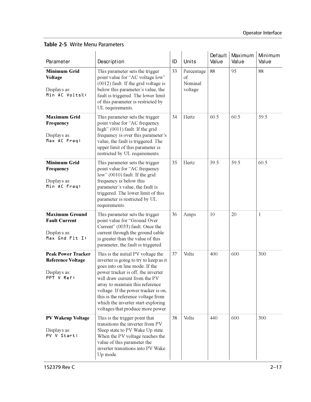
Table 2-5 Write Menu Parameters
|
|
|
| Default | Maximum | Minimum |
Parameter | Description | ID | Units | Value | Value | Value |
|
|
|
|
|
|
|
Minimum Grid | This parameter sets the trigger | 33 | Percentage | 88 | 95 | 88 |
Voltage | point value for “AC voltage low” |
| of |
|
|
|
| (0012) fault. If the grid voltage is |
| Nominal |
|
|
|
Displays as: | below this parameter’s value, the |
| voltage |
|
|
|
Min AC Volts%: | fault is triggered. The lower limit |
|
|
|
|
|
| of this parameter is restricted by |
|
|
|
|
|
| UL requirements. |
|
|
|
|
|
|
|
|
|
|
|
|
Maximum Grid | This parameter sets the trigger | 34 | Hertz | 60.5 | 60.5 | 59.5 |
Frequency | point value for “AC frequency |
|
|
|
|
|
Displays as: | high” (0011) fault. If the grid |
|
|
|
|
|
frequency is over this parameter’s |
|
|
|
|
| |
Max AC Freq: | value, the fault is triggered. The |
|
|
|
|
|
| upper limit of this parameter is |
|
|
|
|
|
| restricted by UL requirements. |
|
|
|
|
|
|
|
|
|
|
|
|
Minimum Grid | This parameter sets the trigger | 35 | Hertz | 59.5 | 59.5 | 60.5 |
Frequency | point value for “AC frequency |
|
|
|
|
|
Displays as: | low” (0010) fault. If the grid |
|
|
|
|
|
frequency is below this |
|
|
|
|
| |
Min AC Freq: | parameter’s value, the fault is |
|
|
|
|
|
| triggered. The lower limit of this |
|
|
|
|
|
| parameter is restricted by UL |
|
|
|
|
|
| requirements. |
|
|
|
|
|
|
|
|
|
|
|
|
Maximum Ground | This parameter sets the trigger | 36 | Amps | 10 | 20 | 1 |
Fault Current | point value for “Ground Over |
|
|
|
|
|
Displays as: | Current” (0033) fault. Once the |
|
|
|
|
|
current through the ground cable |
|
|
|
|
| |
Max Gnd Flt I: | is greater than the value of this |
|
|
|
|
|
| parameter, the fault is triggered. |
|
|
|
|
|
|
|
|
|
|
|
|
Peak Power Tracker | This is the initial PV voltage the | 37 | Volts | 400 | 600 | 300 |
Reference Voltage | inverter is going to try to keep as it |
|
|
|
|
|
Displays as: | goes into on line mode. If the |
|
|
|
|
|
power tracker is off, the inverter |
|
|
|
|
| |
PPT V Ref: | will draw current from the PV |
|
|
|
|
|
| array to maintain this reference |
|
|
|
|
|
| voltage. If the power tracker is on, |
|
|
|
|
|
| this is the reference voltage from |
|
|
|
|
|
| which the inverter start exploring |
|
|
|
|
|
| voltages that produce more power. |
|
|
|
|
|
|
|
|
|
|
|
|
PV Wakeup Voltage | This is the trigger point that | 38 | Volts | 440 | 600 | 300 |
Displays as: | transitions the inverter from PV |
|
|
|
|
|
Sleep state to PV Wake Up state. |
|
|
|
|
| |
PV V Start: | When the PV voltage reaches the |
|
|
|
|
|
| value of this parameter the |
|
|
|
|
|
| inverter transitions into PV Wake |
|
|
|
|
|
| Up mode. |
|
|
|
|
|
|
|
|
|
|
|
|
|
|
|
|
|
|
|
152379 Rev C |
|
|
|
|
|