Operator Interface
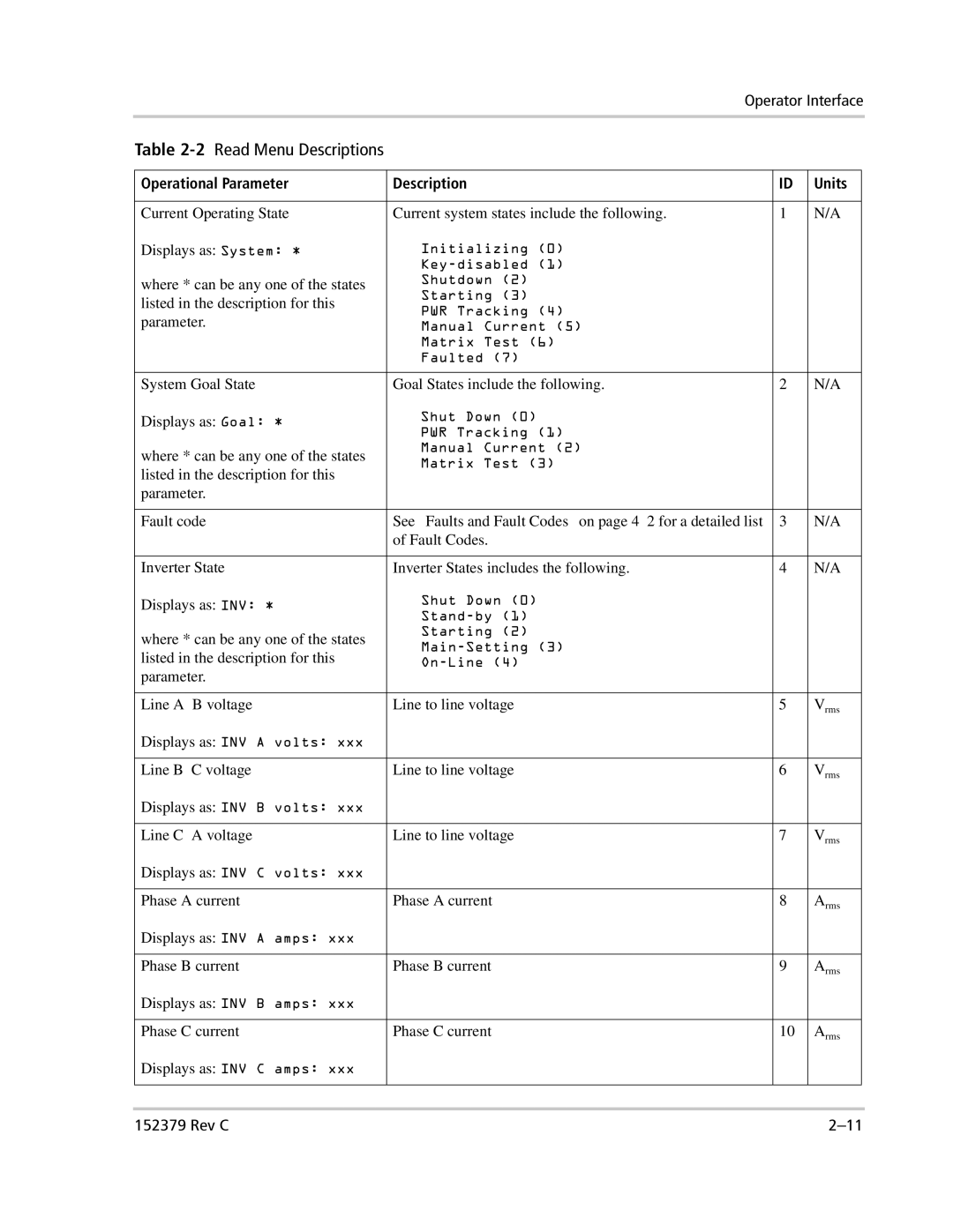
Table 2-2 Read Menu Descriptions
Operational Parameter | Description | ID | Units |
|
|
|
|
|
|
Current Operating State | Current system states include the following. | 1 | N/A |
|
Displays as: System: * | Initializing (0) |
|
|
|
|
|
|
| |
where * can be any one of the states | Shutdown (2) |
|
|
|
Starting (3) |
|
|
| |
listed in the description for this |
|
|
| |
PWR Tracking (4) |
|
|
| |
parameter. |
|
|
| |
Manual Current (5) |
|
|
| |
| Matrix Test (6) |
|
|
|
| Faulted (7) |
|
|
|
|
|
|
|
|
System Goal State | Goal States include the following. | 2 | N/A |
|
Displays as: Goal: * | Shut Down (0) |
|
|
|
PWR Tracking (1) |
|
|
| |
|
|
|
| |
where * can be any one of the states | Manual Current (2) |
|
|
|
Matrix Test (3) |
|
|
| |
listed in the description for this |
|
|
| |
|
|
|
| |
parameter. |
|
|
|
|
|
|
|
|
|
Fault code | See “Faults and Fault Codes” on page | 3 | N/A |
|
| of Fault Codes. |
|
|
|
|
|
|
|
|
Inverter State | Inverter States includes the following. | 4 | N/A |
|
Displays as: INV: * | Shut Down (0) |
|
|
|
|
|
| ||
|
|
|
| |
where * can be any one of the states | Starting (2) |
|
|
|
|
|
| ||
listed in the description for this |
|
|
| |
|
|
| ||
parameter. |
|
|
|
|
|
|
|
|
|
Line | Line to line voltage | 5 | Vrms |
|
Displays as: INV A volts: xxx |
|
|
|
|
|
|
|
|
|
Line | Line to line voltage | 6 | Vrms |
|
Displays as: INV B volts: xxx |
|
|
|
|
|
|
|
|
|
Line | Line to line voltage | 7 | Vrms |
|
Displays as: INV C volts: xxx |
|
|
|
|
|
|
|
|
|
Phase A current | Phase A current | 8 | Arms |
|
Displays as: INV A amps: xxx |
|
|
|
|
|
|
|
|
|
Phase B current | Phase B current | 9 | Arms |
|
Displays as: INV B amps: xxx |
|
|
|
|
|
|
|
|
|
Phase C current | Phase C current | 10 | Arms |
|
Displays as: INV C amps: xxx |
|
|
|
|
|
|
|
|
|
|
|
|
|
|
152379 Rev C |
