Paper Jams
Possible Paper
Jam Areas
Printer Components and Jam Areas
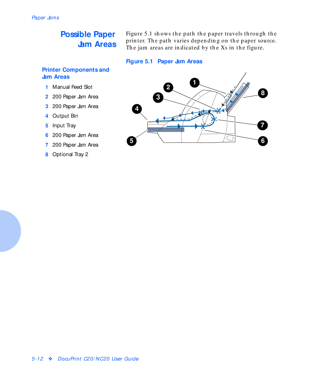
Figure 5.1 shows the path the paper travels through the printer. The path varies depending on the paper source. The jam areas are indicated by the Xs in the figure.
Figure 5.1 Paper Jam Areas
1 Manual Feed Slot |
2
1
2 | 200 Paper Jam Area |
3 | 200 Paper Jam Area |
4 | Output Bin |
3 ![]()
4
8
5 | Input Tray |
6 | 200 Paper Jam Area |
7 | 200 Paper Jam Area |
8 | Optional Tray 2 |
![]() 7
7
5 | 6 |