Chapter 4: Installing the Power Supplies
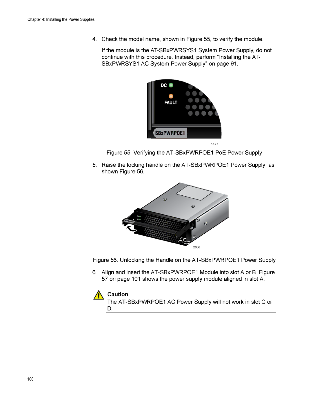
4.Check the model name, shown in Figure 55, to verify the module.
If the module is the
Figure 55. Verifying the AT-SBxPWRPOE1 PoE Power Supply
5.Raise the locking handle on the AT-SBxPWRPOE1 Power Supply, as shown Figure 56.
Figure 56. Unlocking the Handle on the AT-SBxPWRPOE1 Power Supply
6.Align and insert the AT-SBxPWRPOE1 Module into slot A or B. Figure 57 on page 101 shows the power supply module aligned in slot A.
Caution
The AT-SBxPWRPOE1 AC Power Supply will not work in slot C or
D.