SwitchBlade x8106 Chassis Switch Installation Guide
3.Identify the lowest 1/2” screw hole pattern on the rack mounting rails within the space reserved for the
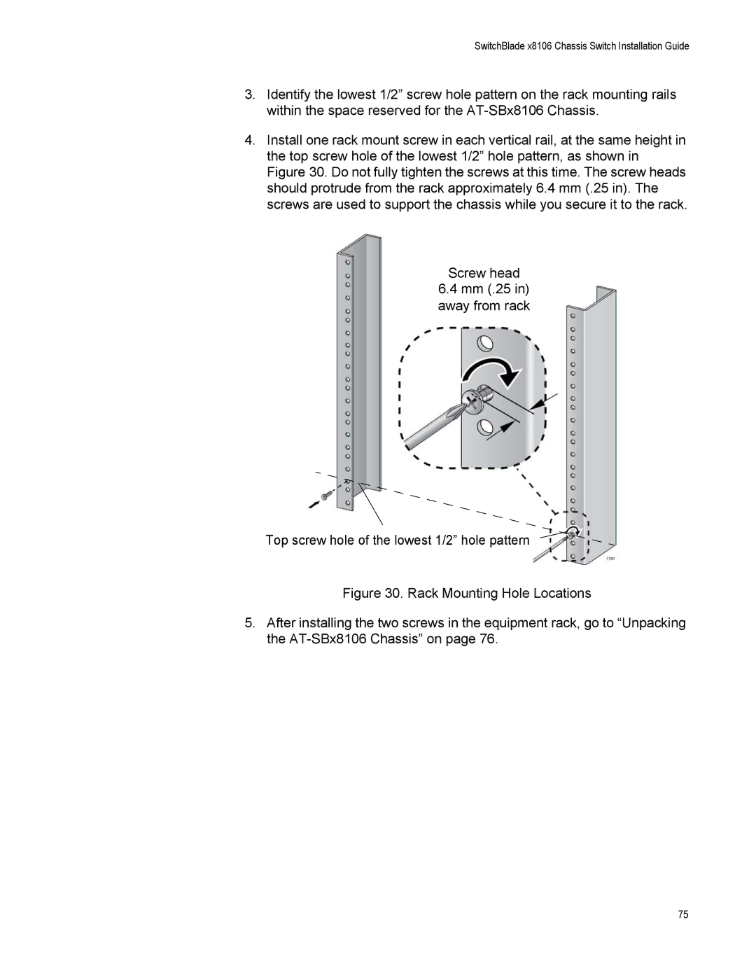
4.Install one rack mount screw in each vertical rail, at the same height in the top screw hole of the lowest 1/2” hole pattern, as shown in Figure 30. Do not fully tighten the screws at this time. The screw heads should protrude from the rack approximately 6.4 mm (.25 in). The screws are used to support the chassis while you secure it to the rack.
Screw head
6.4mm (.25 in) away from rack
Top screw hole of the lowest 1/2” hole pattern
Figure 30. Rack Mounting Hole Locations
5.After installing the two screws in the equipment rack, go to “Unpacking the AT-SBx8106 Chassis” on page 76.
75