SwitchBlade x8106 Chassis Switch Installation Guide
Slot 1 - Line Card |
|
|
|
|
| Slot 2 - Line Card |
|
|
| ||||
Slot 3 - Line Card |
|
|
|
|
| Slot 4 - Line Card |
|
|
|
|
| ||
Slot 5 - Controller |
|
|
|
|
| Slot 6 - Controller |
|
|
|
| |||
| ||||||
Card |
|
|
|
|
| Card |
|
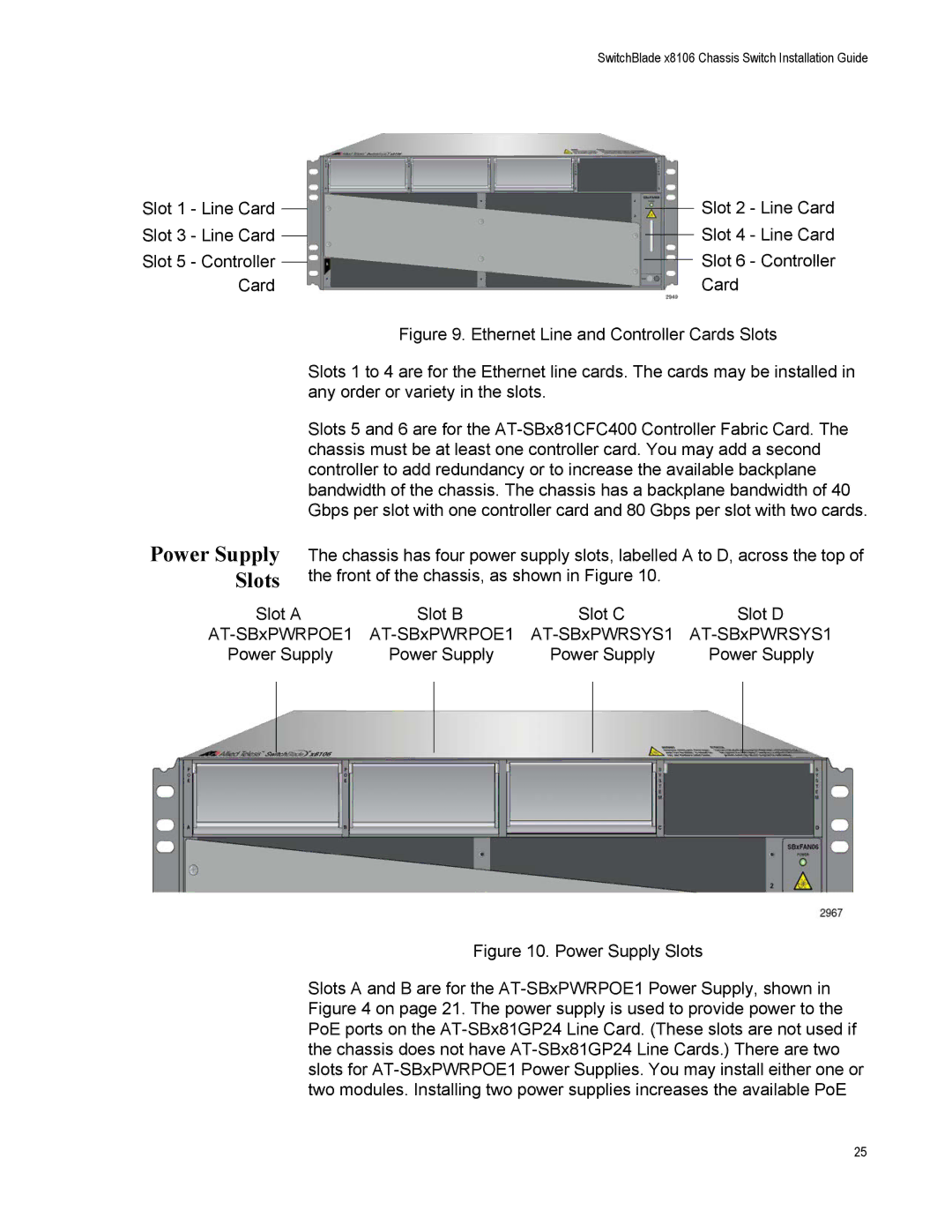
| Figure 9. Ethernet Line and Controller Cards Slots | ||||
Power Supply Slots
Slots 1 to 4 are for the Ethernet line cards. The cards may be installed in any order or variety in the slots.
Slots 5 and 6 are for the
The chassis has four power supply slots, labelled A to D, across the top of the front of the chassis, as shown in Figure 10.
Slot A | Slot B | Slot C | Slot D |
Power Supply | Power Supply | Power Supply | Power Supply |
Figure 10. Power Supply Slots
Slots A and B are for the AT-SBxPWRPOE1 Power Supply, shown in Figure 4 on page 21. The power supply is used to provide power to the PoE ports on the AT-SBx81GP24 Line Card. (These slots are not used if the chassis does not have AT-SBx81GP24 Line Cards.) There are two slots for AT-SBxPWRPOE1 Power Supplies. You may install either one or two modules. Installing two power supplies increases the available PoE
25
