NXD-CV7 and NXT-CV7
AMX Limited Warranty and Disclaimer
FCC Information
Page
Table of Contents
Panel Calibration
Upgrading Modero Firmware
Programming 113
CV7 7 Widescreen Video Touch Panel Kits
FG2258-02
FG2258-01
FG2258-02K
NXT-CV7 and NXD-CV7 front views
CV7 Specifications
Specifications for 7 Widescreen Video Touch Panels
Front Panel Components
Rear Panel Components
Included Accessories
Optional Accessories
Cont
Button Assignments
CV7 Panels Connector Layout
NXA-AVB/ETHERNET CAT5
Product Specifications
NXA-AVB/ETHERNET Specifications
NXA-AVB/ETHERNET Breakout Box FG2254-10
Installing the NXA-AVB/ETHERNET
Rear Components
Panels only
Wiring the NXA-AVB/ETHERNET connectors and cables
Audio In Left Channel
Audio In Right Channel
Wiring the NXA-AVB/ETHERNET for Unbalanced Audio
PWR
Wiring the NXA-AVB/ETHERNET for Balanced Audio
Modero Table Top Cable CA2250-50
Balanced OUT
Modero Table Top Cable Specifications
Wiring information for the Modero Table Top cable
Maximum Table Top Cable Lengths for Modero Panels
Modero Table Top Cable Wiring Table
Wire Connector
NXA-WC80211B/CF 802.11b Wireless Card FG2255-03
Specifications for NXA-WC80211B/CF
Installation of the Wireless Card Table Top Panel
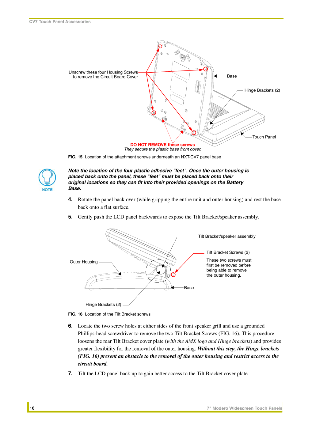
Removing the NXT Outer Housing
Do not Remove these screws
Removal of the outer housing and wireless card location
Slot Card Removal Grooves Card removal grooves
Removing/installing a compact flash card
Closing and Securing the NXT Enclosure
Installation of the Wireless Card WallMount Panel
Removing the existing NXD Outer Housing
Installing the Upgrade Components NXD
Replacing and Securing the NXD Enclosure
NXT-BP Power Pack FG2255-10
Optional Compact Flash Upgrades
NXA-CFSP Compact Flash
NXA-BASE/1 Battery Base Kit FG2255-05K
Specifications for the NXT-BP
Specifications for the NXA-BASE/1
Power Voltage
Installing an NXT-BP into the NXA-BASE/1
Checking the NXT-BP charge
Front
Installing the NXA-BASE/1 below an NXT-CV7 Panel
Battery not shown For illustration purposes Front
Back
NXT-CHG Battery Charger Kit FG2255-50K
Charging the NXT-BP using the NXA-BASE/1
Specifications for NXT-BP and NXT-CHG
Powering the NXT-CHG
Reading the NXT-CHG LED Indicator
Charging the NXT-BP batteries using the NXT-CHG
Recalibrating the batteries
Green Solid
CV7 Touch Panel Accessories
Installing the Internal Components
Installing the No-Button Trim Ring
Unpacking the Panel
Removing the default Button Trim Ring
Installing the Button Trim Ring
Inserting the No-Button Trim Ring
Removing the No-Button Trim Ring
Pre-Wall Installation of the Conduit Box
CB-TP7 conduit box components
Installation of an NXD Touch Panel
Installing the NXD panel within a Conduit Box
Installing the NXD into drywall using Expansion Clips
NXD-CV7 Wall Mount panel dimensions using expansion clips
Installation
Installing the NXD into a Flat Surface using #4 screws
Along the edges
Installation
Wiring Guidelines for the CV7 Panels
Preparing captive wires
Using the PSN NetLinx connector for power
Audio/Video RJ-45 Connections and Wiring
Ethernet 10/100 Base-T RJ-45 Connections and Wiring
Ethernet RJ-45 Pinouts and Signals
Audio/Video RJ-45 Pinout Information
Connecting and Using USB Input Devices
RJ-45 wiring diagram
Installation
Calibrating the Modero Panel
Second press/hold
Testing your Calibration
Touch Panel Calibration Screens
Configuring Communication
Modero Setup and System Connection
Protected Setup
Configuring and Using USB with a Virtual Master
Setup the Panel and PC for USB Communication
Confirm the Installation of the USB Driver on the PC
USB System Connection page using a USB Connection Type
Installed prior to setting up a USB connection to the panel
Confirm and View the current AMX USB device connections
Device Manager dialog showing USB device
Before beginning
Confirm and View the current AMX USB device connections
Secondary Connection Page Wireless Access Overview
IP Routing
Hot Swapping
Configuring Communication
Configuring a Wireless Network Access
Configure the Panel’s Wireless IP Settings
Wireless communication using a Dhcp Address
Wireless communication using a Static IP Address
Configure the Card’s Wireless Security Settings
Following sections use an NXA-WAP200G and the target WAP
Procedures
Secondary Connection page Wireless Settings section
These WEP Key identifier values must match for both devices
WEP Key # Keyboard
Configuring a Wired Ethernet Connection
Configure the Panel’s Wired IP Settings
Configuring Communication
Choose a Master Connection Mode Setting
Configure an Ethernet Connection Type
Obtained From NetLinx Master
These must match
Configuring Communication
URL List dialog
Using G4 Web Control to Interact with a G4 Panel
G4 Web Control
Accessing the NetLinx Master via an IP Address
Using your NetLinx Master to Control the G4 panel
Web Control VNC installation and Password entry screens
Connection Details dialog
Configuring Communication
Configure the panel for a USB Connection Type
Upgrading the Modero Firmware via the USB port
Prepare NetLinx Studio for communication via the USB port
Confirm and Upgrade the firmware via the USB port
Default Modero panel value is
Select the panel’s KIT file from the Files section
Upgrading the Modero Firmware via Ethernet IP Address
Prepare the Master for communication via an IP
Assigning Communication Settings and TCP/IP Settings
Prepare the panel for communication via an IP
Verify and Upgrade the panel firmware via an IP
Select the panel’s KIT file from the Files section FIG
Device and System values
Setup Navigation Buttons
Setup Navigation Button Elements
Setup
Setup Page Elements
Display/Panel Timeout
Timeout
Connection Status
Inactivity Page Flip
Project Information
Project Information Page Elements
Panel Information
Panel Information Page Elements
Time & Date Setup
RAM
Time & Date Setup Page Elements
Time Date Refresh/Set
Time Display fields
Date Display fields
Volume
Volume Page Elements
Protected Setup
Video Adjustment
Default Panel Sounds
Supported sampling rates for WAV
Video Setup Page Elements
Battery Base
Battery Base Page Elements
Low Battery Warning
Charge Status
Reaches a point where it needs to be recalibrated
Battery Status fields
Limit
Protected Setup Navigation Buttons
Protected Setup Navigation Button Elements
Protected Setup
Protected Setup Page Elements
Reboot Panel
Device Number
System Recovery
Slider
G4 Web Control Settings
G4 Web Control
G4 Web Control Page Elements
Sensor Setup
G4 Web Control Timeout
Sensor Setup Page Elements
Dim Mode Minimum
Light Sensor
Motion Sensor
Wake Panel On Motion
Sense
Password Setup
Password Setup Page Elements
Panel Password
Change
Calibration
Secondary Connection
Secondary Connection Page Elements
Access Point MAC
Wireless Settings
Address
108
System Connection
System Connection Page Elements
Full Duplex
Master Connection
ICSNet is not a supported option on this panel
Firmware Pages and Descriptions 112
Commands
Commands
Button Assignments
Sendcommand Panel,@DPG-Popup1Group1
@PDR-popup page namereset flag
Sendcommand Panel,@PDR-Popup11
Sendcommand Panel,@PHE-Popup1Slide to Left
Commands
Sendcommand Panel,@PPM-Popup1Modal
Sendcommand Panel,@PPM-Popup11
Sendcommand Panel,@PPN-Popup1Main
Sendcommand Panel,@PPN-Popup1
Sendcommand Panel,@PSE-Popup1Slide from Left
Sendcommand Panel,@PSP-Popup1100,0
Sendcommand Panel,@PST-Popup150
Sendcommand Panel,PAGE-Page1
Sendcommand Panel,PPOF-Popup1Main
Sendcommand Panel,PPOF-Popup1
Sendcommand Panel,PPOG-Popup1Main
Sendcommand Panel,PPOG-Popup1
Programming Numbers
RGB triplets and names for basic 88 colors
RGB Values for all 88 Basic Colors
Index No Name Red Green Blue
120
Default Font Styles and ID Numbers
Font styles and ID numbers
Font ID # Font type Size
Variable Fonts start at
Border styles and Programming numbers
Border Styles and Programming Numbers
TPD4 Border Styles by Name
Border styles
Modero Widescreen Touch Panels 123
Button Commands
Button Commands
Sendcommand Panel,BCB-500.504&510,1,12
Sendcommand Panel,BCF-500.504&510.515,1,12
Sendcommand Panel,BCF-500.504&510.515,1,Yellow
Sendcommand Panel,BCF-500.504&510.515,1,#F4EC0A63
Button Commands
Sendcommand Panel,BFB-500,Momentary
Sendcommand Panel,BIM-500,AAAAAAAAAA
Sendcommand Panel,BLN-500,55
BIM-vt addr range,input mask
BLN-vt addr range,button states range,number
Sendcommand Panel,BMC- 150,1,1,315,1,%BR%FT%TX%BM%IC%CF%CT
BMC
BMF-vt addr range,button states range,data
BMF
Modero Widescreen Touch Panels 131
Sendcommand Panel,BMI-530,1&2,newMac.png
Sendcommand Panel,BML-500,20
Sendcommand Panel,BMP-500.504&510.515,1,bitmap.png
BNC-vt addr range,command value
Sendcommand Panel,BNN-973,192.168.169.99
Sendcommand Panel,BNT-973,5000
Sendcommand Panel,BOP-500.504&510.515,1,200
Sendcommand Panel,BOP-500.504&510.515,1,#C8
Sendcommand Panel,BOR-500.504&510.515,10
Sendcommand Panel,BOR-500.504&510,AMX Elite -M
Sendcommand Panel,BOS-500,1,1
Sendcommand Panel,BPP-500,1
Sendcommand Panel,BRD-500.504&510.515,1&2,Quad Line
Sendcommand Panel,BSF-500,1
Sendcommand Panel,BSM-500
Sendcommand Panel,BSO-500,1&2,music.wav
Sendcommand Panel,BVL-500,0
Sendcommand Panel,BVN-500,191.191.191.191
BVP-vt addr range,network password
Sendcommand Panel,BVP-500,PCLOCK
Sendcommand Panel,CPF-500
Send Command Panel,DPF-409,Prev
ENA-vt addr range,command value
Sendcommand Panel,ENA-500.504&510.515,0
Sendcommand Panel,GDI-7,128
Sendcommand Panel,GIV-500,3
Sendcommand Panel,GLH-500,1000
Sendcommand Panel,GLL-500,150
Sendcommand Panel,GRD-500,200
Sendcommand Panel,GRU-500,100
Sendcommand Panel,GSC-500,12
Sendcommand Panel,GSN-500,Ball
Sendcommand Panel,ICO-500.504&510.515,1&2,1
Sendcommand Panel,JSB-500.504&510.515,1&2,1
Sendcommand Panel,JSI-500.504&510.515,1&2,1
ICO-vt addr range,button states range,icon
Sendcommand Panel,JST-500.504&510.515,1&2,1
Send Command Panel,MBT-1
Send Command Panel,MDC
SHO-vt addr range,command value
Sendcommand Panel,TEC-500.504&510.515,1&2,12
Sendcommand Panel,TEF-500.504&510.515,1&2,Soft Drop
Sendcommand Panel,TXT-500.504&510.515,1&2,Test Only
TEC-vt addr range,button states range,color
Sendcommand Panel,UNI-500,1,0041
Sendcommand TP,UNI-1,0,0041
UNI-vt addr range,button states range,unicode text
UNI
Text Effect Names
Text Effects
Button Query Commands
Defineevent
Button Query Commands
Send Command Panel,?BCB-529,1
Custom Event Fields
?BCB-vt addr range,button states range
Send Command Panel,?BCF-529,1
Send Command Panel,?BCT-529,1
Get the current fill ?BCF-vt addr range,button states range
?BCT-vt addr range,button states range
Send Command Panel,?BMP-529,1
Send Command Panel,?BOP-529,1
?BMP-vt addr range,button states range
?BOP-vt addr range,button states range
Send Command Panel,?BRD-529,1
Send Command Panel,?BWW-529,1
?BRD-vt addr range,button states range
?BWW-vt addr range,button states range
Send Command Panel,?FON-529,1
Send Command Panel,?ICO-529,1&2
?FON-vt addr range,button states range
?ICO-vt addr range,button states range
Send Command Panel,?JSB-529,1
Send Command Panel,?JSI-529,1
?JSB-vt addr range,button states range
?JSI-vt addr range,button states range
Send Command Panel,?JST-529,1
Send Command Panel,?TEC-529,1
?JST-vt addr range,button states range
?TEC-vt addr range,button states range
Send Command Panel,?TEF-529,1
Send Command Panel,?TXT-529,1
?TEF-vt addr range,button states range
?TXT-vt addr range,button states range,optional
Panel Runtime Operation Commands
Panel Runtime Operations
Send Command Panel,@AKP-12345678ENTER Password
Send Command Panel,@AKR
Send Command Panel,BEEP
Send Command Panel,BRIT-50
Send Command Panel,@EKP-33333333Enter Password
Send Command Panel,PKEYP-123456789
Send Command Panel,@PKP-1234567ENTER Password
Send Command Panel,SETUP
Send Command Panel,@SOU-Music.wav
Send Command Panel,@TKP-999.222.1211Enter Phone
Send Command Panel,TPAGEON
Send Command Panel,TPAGEOFF
Input Commands
Input Commands
Embedded codes
Embedded Codes
Decimal numbers Hexidecimal values Virtual keystroke
Panel Setup Commands
Panel Setup Commands
Dynamic Image Commands
Dynamic Image Commands
RAF-resource name,data
Embedded Codes Parameter Description
Troubleshooting Information
Symptom Solution Updated my panel firmware but
My Battery Base page doesn’t
My NXT-BP battery pack is
Life indicator
Symptom Solution
Connecting
Was using the power from
NXA-BASE/1 battery base to
My battery from within an
Powered panel
NXA-BASE/1 connected to a
My WEP doesn’t seem to be
After downloading a panel file or Symptoms include
Providing power
Connected to my System Master
Only one shows up
Troubleshooting 168
Text Formatting Codes for Bargraphs/Joysticks
Bargraph Text Code Inputs
Formatting Code Operations
Example
Text Area Input Masking
Input mask character types
Character Types
Character Masking Rule
Input mask ranges
Input mask next field characters
Input mask operations
Input mask literals
Input mask output examples
Output Examples
Common Name Input Mask
URL Resources
Special escape sequences
Escape Sequences
Sequence Panel Information
174
Appendix Widescreen Modero Touch Panels 175
RevisionLast15/08/04