Modero
AMX Limited Warranty and Disclaimer
FCC Information
Page
Table of Contents
Panel Calibration
Upgrading Modero Firmware
Programming 121
181
Table of Contents 1200V Modero Video Touch Panels
Modero Video Touch Panels 1200V-Series
Modero Video Touch Panels
FG2251-60K
FG2250-60K
Product Specifications NXD-1200V and NXT-1200V
1200V Panel Specifications
Button Assignments
Front Panel Components
Rear Panel Components
Included Accessories
Cont
Operating / Storage
Environment
1200V-Series Modero Connectors
Cleaning the Touch Overlay
Connecting and Using Input Devices
Product Specifications
NXA-AVB/ETHERNET Specifications
NXA-AVB/ETHERNET Breakout Box FG2254-10
Installing the NXA-AVB/ETHERNET
Rear Components
Panels only
Wiring the NXA-AVB/ETHERNET connectors and cables
Audio In Left Channel
Audio In Right Channel
Wiring the NXA-AVB/ETHERNET for Unbalanced Audio
Wiring the NXA-AVB/ETHERNET for Balanced Audio
Modero Table Top Cable Specifications
Connectors
Modero Table Top Cable CA2250-50
Balanced OUT
Wiring information for the Modero Table Top cable
Maximum Table Top Cable Lengths for Modero Panels
Modero Table Top Cable Wiring Table
Wire Connector
To Touch Panel To Breakout Box
Installing CAT5 Suppression Ferrites
Table Top Cable Specification Elements
Optional Compact Flash Memory Upgrades
NXA-CFTP Compact Flash FG2116-2x
NXA-PCI80211G Wireless Card FG2255-04
NXA-PCI80211G Specifications
Description
Media Access Technique
Antenna Type
Bus Interface
Frequency Range
Installation and Upgrade of the Internal NXT Components
Remove the existing NXT Outer Housing
Receiver Sensitivity
Security
Install the 802.11g mini-PCI Wireless Card
Location of the NXA-PCI80211G wireless card on the NXT board
Location of the mini-PCI card connector on main board
Install the Compact Flash Memory Card upgrade
Location of the Compact Flash card and I/O plate on NXT
Installation and Upgrade of the Internal NXD Components
Remove the existing NXD Outer Housing
Close and Resecure the NXT Panel Enclosure
Install the new 802.11g mini-PCI Wireless card NXD
Install the new Compact Flash Memory card NXD
Close and Resecure the NXD Panel Enclosure
Location of the Compact Flash card and I/O plate on NXD
NXT-BP Power Pack FG2255-10
NXA-BASE/B Battery Base Kit FG2255K
NXT-BP Specifications
Power Voltage
Checking the NXT-BP battery charge
NXA-BASE/B Specifications
Installing the NXA-BASE/B to an NXT Modero Panel
NXA-BASE/B showing Panel Interface and connector locations
Installing an NXT-BP into the NXA-BASE/B
Top view
Front
NXT-CHG Battery Charger Kit FG2255-50K
Charging the NXT-BP batteries with the NXA-BASE/B
Powering the NXT-CHG
Reading NXT-CHG LED Indicator
NXT-BP and NXT-CHG Specifications
Charging the NXT-BP batteries using the NXT-CHG
Recalibrating the batteries
Green Solid
Touch Panel Accessories 1200V Modero Video Touch Panels
Installing the Internal Components
Unpacking the Panel
Upgrading to the MB-TP12 Vesa Mounting Kit
Installing the MP-TP12 Back Box
Removing the Original Modero Back Box
Cable Installation for the MP-TP12 Back Box
Finalizing the installation
8020MM 5264MM 5590MM 6166MM
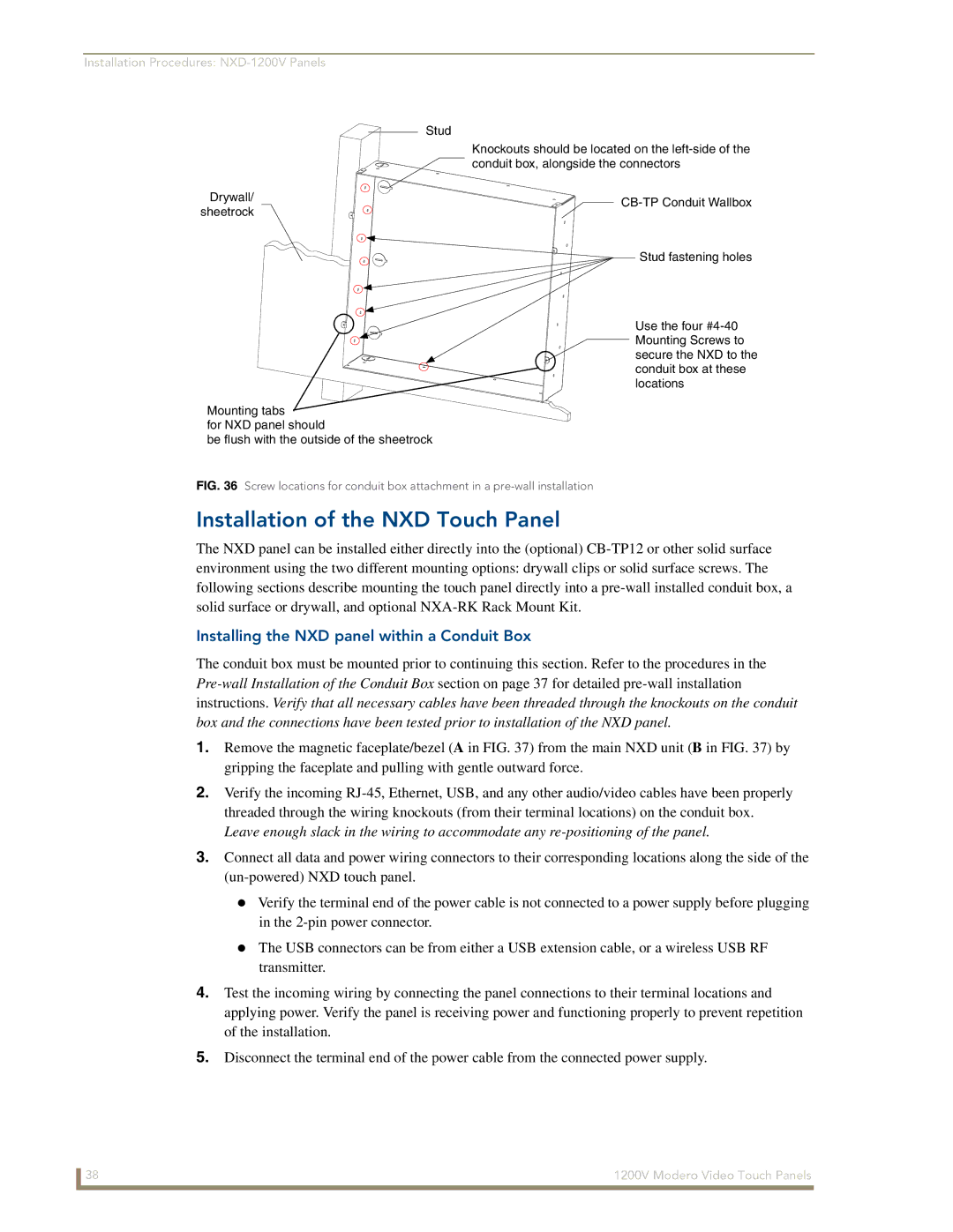
Pre-wall Installation of the Conduit Box
Rear plastic cover rear view
Clip Facing UP
USE only AMX Provided #8-32 screws
Installation of the NXD Touch Panel
Installing the NXD panel within a Conduit Box
Surface
Installing the NXD into drywall using Expansion Clips
Notches are
Installing the NXD into a Flat Surface using #4 screws
Installation Procedures NXD-1200V
Screws not included
Installing an NXD into an optional Rack Mount Kit NXA-RK12
Insert the main 12-inch Modero unit into an NXA-RK12 FIG
Wiring Guidelines for the 1200V Panels
Preparing captive wires
Audio/Video Port Connections and Wiring
Wiring a power connection
Pin Wire Color Function Polarity
Audio/Video RJ-45 Pinout Information
Ethernet/RJ-45 Port Connections and Wiring
Ethernet RJ-45 Pinouts and Signals
Pin Signals Connections Pairing Color
Page
Second press/hold Accesses the Setup
Calibrating the Modero Panel
Testing your Calibration
Touch Panel Calibration Screens
Configuring Communication
Modero Setup and System Connection
Modero connection information
Configuring and Using USB with a Virtual Master
Setting up the Panel and PC for USB Communication
Confirming the Installation of the USB Driver on the PC
System Settings page using a USB Connection Type
Navigate back to the System Settings
Confirm and View the current AMX USB device connections
Device Manager dialog showing USB device
Assigning Communication Settings for a Virtual Master
Using USB for Virtual Master communication
Wireless Settings Page Wireless Access Overview
IP Routing
Hot Swapping
Configuring a Wireless Connection
Configuring the Panel’s Wireless IP Settings
Wireless communication using a Dhcp Address
Wireless communication using a Static IP Address
Configuring the Card’s Wireless Security Settings
An NXA-WAP200G and the target WAP
Configuring Communication
Wireless Settings page Wireless Settings section
These WEP Key identifier values must match for both devices
Configuring Communication
Configuring a Wired Ethernet Connection
Configuring the Panel’s Wired IP Settings
Choosing a Master Connection Mode Setting
Configuring the Ethernet Connection Type
Master Connection Virtual Master communication over Ethernet
Sample System Settings page for Virtual Master communication
These must match
Configuring Communication
Resides on the same Subnet as itself
Using G4 Web Control to Interact with a G4 Panel
G4 Web Control
Configuring Communication
Using your NetLinx Master to control the G4 panel
Web Control VNC installation and Password entry screens
Configuring Communication
Configure the panel for a USB Connection Type
Upgrading the Modero Firmware via the USB port
Prepare NetLinx Studio for communication via the USB port
Confirm and Upgrade the firmware via the USB port
Default Modero panel value is
Using USB for a Virtual Master transfer
Upgrading the Modero Firmware via an IP Address
Prepare the Master for communication via an IP
Prepare the panel for communication via an IP
Verify and Upgrade the panel firmware via an IP
NetLinx Workspace window showing connected Modero panel
Upgrading Accessory Devices via the USB
Device value and System number must match the values
Target Panel Device #
NetLinx Studio Online Tree tab
Battery Base
Prepare the NXA-BASE/B for firmware transfer via USB
Upgrade the NXA-BASE/B firmware via USB
Select the battery base’s Kit file from the Files section
Upgrading Accessory Devices via an IP Address
Prepare the NXA-BASE/B for firmware transfer via an IP
Upgrade the NXA-BASE/B firmware via an IP
Upgrading Modero Firmware
Upgrading Modero Firmware 1200V Modero Video Touch Panels
Setup Navigation Buttons
Setup Navigation Button Elements
Setup
Setup Page Elements
Display/Panel Timeout
Timeout
Connection Status
Inactivity Page Flip
Project Information
Project Information Page Elements
Panel Information
Panel Information Page Elements
Time & Date Setup
Time & Date Setup Page Elements
RAM
Volume
Volume Page Elements
Time Display fields
Date Display fields
Protected Setup
Supported sampling rates for WAV
Supported WAV Sampling Rates
Video Adjustment Slide-Out Option Bar
Video Adjustment Video Adjustment
Video Adjustment Page Elements
Battery Base
Battery Base Page Elements
Protected Setup Navigation Buttons
Battery Power Brightness Limit
Modero Protected Setup Navigation Buttons
Protected Setup
Protected Setup Navigation Button Elements
Protected Setup Page Elements
Reboot Panel
System Recovery
Device Number
Keyboard Layout
Button
Slider
G4 Web Control
G4 Web Control Page Elements
G4 Web Control Settings
G4 Web Control Timeout
Sensor Setup
Sensor Setup Page Elements
Light Sensor
Light Level field
Using the Automated Brightness Control feature DIM Mode
Dim Mode Minimum
Motion Sensor
Wake Panel On Motion
Password Setup
Password Setup
Password Setup Page Elements
Panel Password
Calibration
Change
Wireless Settings
Wireless Settings Page Elements
IP Settings
Access Point MAC
Address
116 1200V Modero Video Touch Panels
1200V Modero Video Touch Panels 117
System Settings
System Settings Page Elements
Full Duplex
Master Connection
Information on using the System Settings
Commands
Commands
Button Assignments
@APG
@DPG
@PDR
@PHE
@PHP
Commands
@PPM
@PPN
@PPT
@PPX
@PSE
@PSP
@PST
Ppof
Ppog
Ppon
Programming Numbers
RGB triplets and names for basic 88 colors
RGB Values for all 88 Basic Colors
Index No Name Red Green Blue
128 1200V Modero Video Touch Panels
Default Font Styles and ID Numbers
Font styles and ID numbers
Font ID # Font type Size
Border styles
TPD4 Border Styles by Name
Border styles
1200V Modero Video Touch Panels 131
Button Commands
Button Commands
ANI
APF
Sendcommand Panel,BAT-520,1,Enter City
Sendcommand Panel,BAU-520,1,00770062
BAT
BAT-vt addr range,button states range,new text
BCB
BCF
BCT
BDO
BFB
BIM
Entry is required
BLN
Sendcommand Panel,BMC-150,1,1,315,1,%BR%FT%TX%BM%IC%CF%CT
BMC
BMF
BMF-vt addr range,button states range,data
1200V Modero Video Touch Panels 139
BMI
BML
BMP
BNC
BNN
BNT
BOP
BOR
BOS
BPP
BRD
BSF
BSM
BSO
BVL
BVN
BVP
BVT
CPF
DPF
ENA
FON
GDI
GIV
GLH
GLL
GRD
GRU
GSC
GSN
ICO
JSB
JSI
JST
MBT
Pass data
MDC
TEC
TEF
Effect names
TXT
Sendcommand Panel,UNI-500,1,0041
Sendcommand TP,UNI-1,0,0041
UNI
UNI-vt addr range,button states range,unicode text
Text Effect Names
Text Effects
Button Query Commands
Defineevent
Button Query Commands
Custom Event Fields
Field Description
?BCB
?BCF
?BCT
?BMP
?BOP
?BRD
?BWW
?FON
?ICO
?JSB
?JSI
?JST
?TEC
Send Command Panel,?TEF-529,1
Send Command Panel,?TXT-529,1
?TEF
?TEF-vt addr range,button states range
Panel Runtime Operation Commands
Panel Runtime Operations
@AKP
@AKR
Beep
Brit
Setup
@EKP
Pkeyp
@PKP
@SOU
@TKP
Tpageon
Tpageoff
Input Commands
Input Commands
CAL
KPS
SLT
VKS
Embedded Codes
Embedded Codes
Decimal numbers Hexidecimal values Virtual keystroke
Panel Setup Commands
Panel Setup Commands
Dynamic Image Commands
Dynamic Image Commands
RAF-resource name,data
Programming 172 1200V Modero Video Touch Panels
Troubleshooting Information
USB
Symptom Solution Updated my panel firmware but
My Battery Base page doesn’t
My NXT-BP battery pack is
Life indicator
Symptom Solution
Power supply
My batteries from within an
NXA-BASE/B connected to a
Symptom Solution After downloading a panel file or
Battery Base button doesn’t
Behaves strangely
Touch panel
Text Formatting Codes for Bargraphs/Joysticks
Bargraph Text Code Inputs
Formatting Code Operations
Example
Text Area Input Masking
Input mask character types
Character Types
Character Masking Rule
Input mask ranges
Input mask next field characters
Input mask operations
Input mask literals
Input mask output examples
Output Examples
Common Name Input Mask
URL Resources
Special escape sequences
Escape Sequences
Sequence Panel Information
Appendix a 182 1200V Modero Video Touch Panels
Appendix a 1200V Modero Video Touch Panels 183
Appendix a 184 1200V Modero Video Touch Panels
Appendix Modero Widescreen Touch Panels 185
It’s Your World Take Control