The Converged Network Analyzer
Sites A and B will move away from the outage in less than a second, preventing unintelligibility in the audio bearer, or outages in the voice signaling.
Simultaneous monitoring of all paths
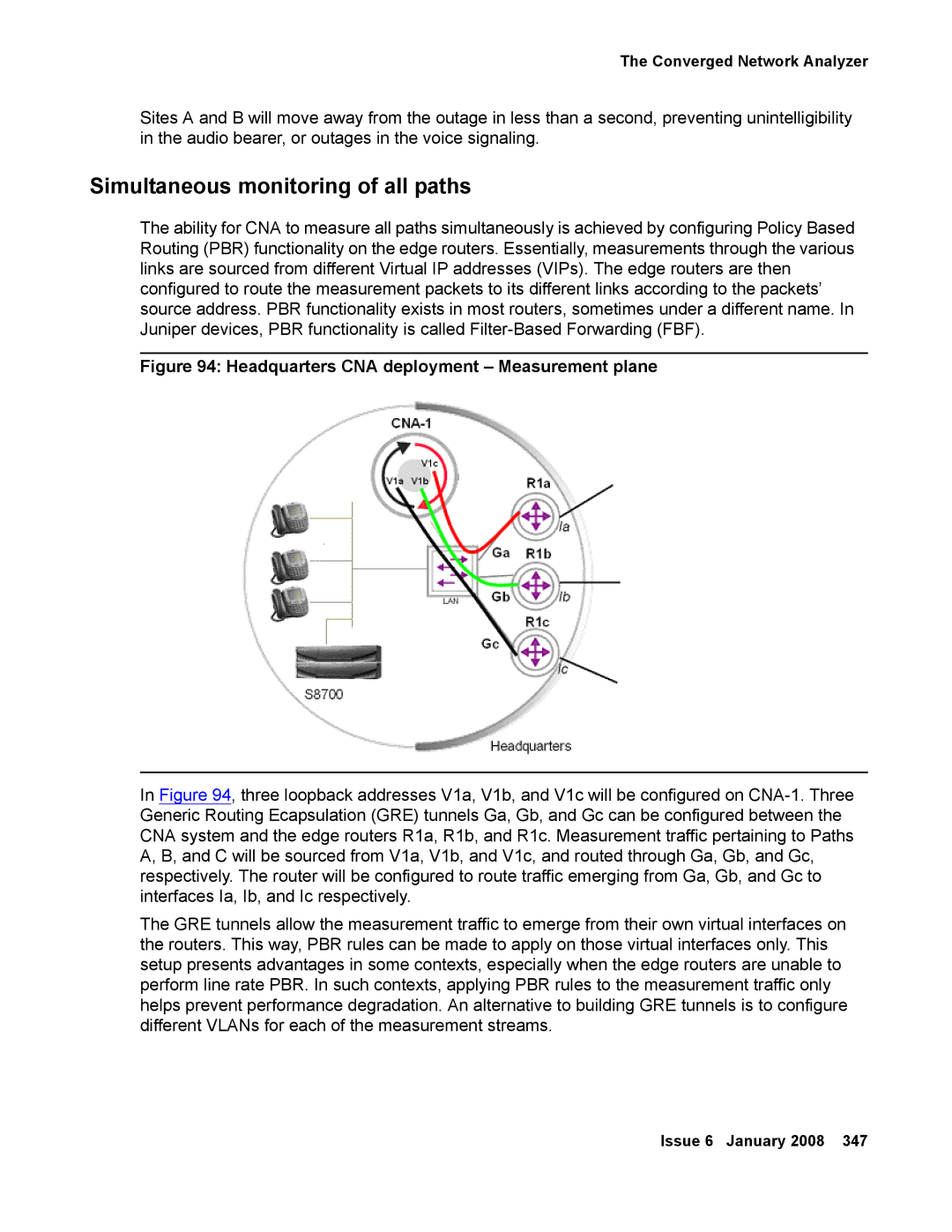
The ability for CNA to measure all paths simultaneously is achieved by configuring Policy Based Routing (PBR) functionality on the edge routers. Essentially, measurements through the various links are sourced from different Virtual IP addresses (VIPs). The edge routers are then configured to route the measurement packets to its different links according to the packets’ source address. PBR functionality exists in most routers, sometimes under a different name. In Juniper devices, PBR functionality is called
Figure 94: Headquarters CNA deployment – Measurement plane
In Figure 94, three loopback addresses V1a, V1b, and V1c will be configured on
The GRE tunnels allow the measurement traffic to emerge from their own virtual interfaces on the routers. This way, PBR rules can be made to apply on those virtual interfaces only. This setup presents advantages in some contexts, especially when the edge routers are unable to perform line rate PBR. In such contexts, applying PBR rules to the measurement traffic only helps prevent performance degradation. An alternative to building GRE tunnels is to configure different VLANs for each of the measurement streams.
