Call processing
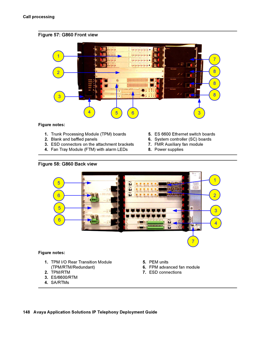
Figure 57: G860 Front view
1
2
3
7
8
8
8
| 4 | 5 | 6 |
| 3 |
Figure notes: |
|
|
|
| |
1. | Trunk Processing Module (TPM) boards |
| 5. | ES 6600 Ethernet switch boards | |
2. | Blank and baffled panels |
|
| 6. | System controller (SC) boards |
3. | ESD connectors on the attachment brackets | 7. | FMR Auxiliary fan module | ||
4. | Fan Tray Module (FTM) with alarm LEDs |
| 8. | Power supplies | |
|
|
|
|
|
|
|
|
|
|
|
|
Figure 58: G860 Back view
5
6
5
6
|
|
| 7 |
Figure notes: |
|
| |
1. | TPM I/O Rear Transition Module | 5. | PEM units |
| (TPM/RTM/Redundant) | 6. | FPM advanced fan module |
2. | TPM/RTM | 7. | ESD connections |
3.ES/6600/RTM
4.SA/RTMs
1
2
3
4