Manuals
/
Brands
/
Computer Equipment
/
Network Router
/
Cables to Go
/
Computer Equipment
/
Network Router
Cables to Go
CDM-570, CDM-570L
Feature Configuration
1
38
146
146
Download
146 pages, 4.86 Mb
Menu Descriptions
3-4
Vipersat CDM-570/570L User Guide
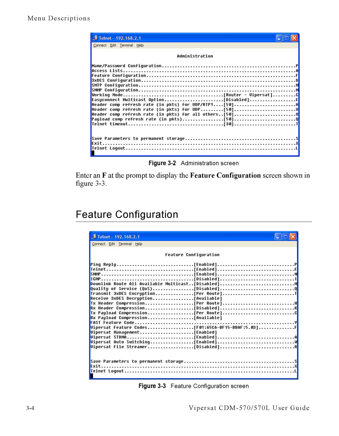
Figure 3-2
Administration screen
Enter an
F
at the prompt to display the
Feature Configuration
screen shown in
figure 3-3.
Feature Configuration
Figure 3-3
Feature Configuration screen
Contents
Main
Page
Page
Page
Page
Page
Table of Contents
General
Quick Start Configuration
Using the Command Line Interface (CLI)
Network Addressing
Automatic Switching
Dynamic Power Control
Network Migration
Glossary
Page
List of Figures
Chapter 2 Figures
Chapter 3 Figures
Appendix A Figures
Appendix B Figures
Appendix C Figures
Appendix D Figures
G
How to Use This Manual
Manual Organization
Conventions and References
Page
Product Description
Introduction
Modem Features
Router Features
Network and Bandwidth Management
Dynamic SCPC (dSCPC)
Turbo Product Coding
Header Compression
Payload Compression
New in this Release
1.5.3 Release
Page
Customer Support
Contact Information
Return Material Authorization
Reader Comments / Corrections
Page
QUICK START CONFIGURATION
Introduction
Page
Initial Configuration
Terminal Connection
Network Role
Setting Vipersat CDM-570/570L Operating Parameters
Set the Feature Configuration
Page
Page
Set the IP Address
Configure the Route Table
Page
Set the Satellite Modem Configuration
Set the Vipersat Configuration
Page
USING THE COMMAND LINE INTERFACE (CLI)
Common Screen Commands
Save Parameters to Permanent Storage
Page
Menu Descriptions
Main menu
Administration
Feature Configuration
Vipersat Feature Codes menu
Vipersat Management
Page
Vipersat Configuration
STDMA Mode
STDMA
STDMA Tx Rate
Hub Type
Page
Group ID
Low Data Rate Fast Acquisition
Burstmap Multicast IP
Outbound IP
Cycles Per Burst Map
Slot Guardband
Slot Preamble Length
Slot Data Length
Slot Cycle Length
Slot Start in Cycle
Set Remotes
Page
Page
Page
Page
Page
STDMA Statistics
Show Hub Statistics
STDMA/SCPC Automatic Switching
Auto Switching
Current WAN Transmit Mode
Voice & Video Application Switching
ToS Switch Detection
QoS Switch Detection
Page
Page
Load Switching
Page
Page
ToS Switching Parameters
Page
Page
Unit Role
Expansion Unit
Network ID
Unit Name
Receive Multicast Address
Managing IP Address
Primary Heart Beat
Home State Revert
Dynamic Power Control Configuration
DPC Enabled
Calibrated Data Rate
Nominal Power Level
Max Power
Min Power
Max Step Down Power
Max Step Up Power
Target EbNo
Targ et Ra nge
Speed Up EbNo
Target DPC Address
Set Home State Parameters
Set Current Configuration as Home State
Force Modem to Home State
STDMA State
Transmit Frequency
Transmit Data Rate
Transmit FEC Type
Transmit Coding Rate
Page
Receive Data Rate
Receive FEC Type
Receive Coding Rate
Receive Modulation Type
Vipersat Summary
Vipersat Migration
Page
Page
NETWORK ADDRESSING
The OSI Reference Model
Layers 1 3
Page
Binary Math
Page
IP Addressing
IP Address Classes
Page
Private Network IP Addresses
Network Address Translation (NAT)
Subnets
Subnet Mask
Network Segments
Default Gateways
MAC Addresses
Page
AUTOMATIC SWITCHING
Bandwidth Allocation and Load Switching
Load Switching
Bandwidth Allocation and Load Switching by the STDMA Controller:
Page
Page
Page
Load Switching Process
Load Switching by a Remote
Determining Need-for-Change
Load Switch Example
Page
Reduced data flow in switched mode (SCPC)
Application switching
Page
Type of Service (ToS) Switching
Entry Channel Mode (ECM) Switching
Applications Switching
Appendix B - Automatic Switching B-15
ECM switch recovery < 3 minutes
Figure B-5
ECM Switch Recovery < 3min.
Entry Channel Mode (ECM) Switching
ECM switch recovery > 3 minutes
Figure B-6
B-16 Vipersat CDM-570/570L User Guide
ECM Switch Recovery > 3min.
DYNAMIC POWER CONTROL
Introduction
Description
Page
Data Rate
Power Level
Page
Page
NETWORK MIGRATION
Upgrading CDM-570/CDD-564 Series Modems to Firmware Version 1.5.3
Page
Firmware Upgrade
Upgrade Overview
Required Support Utilities and Firmware
Basic Steps
Migration Procedure
Getting Information with VLOAD
Page
Upgrade Router to v1.5.3
Save and Reboot to Latest
Get Information for Router v1.5.3
Upgrade Base Modem to v1.5.1
Upgrade Image 1 on Base Modem to v1.4.5
Upgrade Image 1 on Base Modem to v1.5.1
Download Base Modem v1.5.1 to Image 2
Download Router v1.5.3 to Image 2
Completing Migration
Picking Up Straggler/Offline Remotes
Setting v1.5.2 Compatibility in Hub Modems
Page
Page
Page
G
A
stabilization of the HPAs RF output power.
B
C
D
E
F
G
H
I
K
L
M
N
O
P
contains information on messages received or lost.
Q
R
S
T
U
V