Chapter 3: Installation
|
| TO | |||
| SmartSwitch RJ45 Port | ||||
| RX+ |
|
|
|
|
| 1 |
|
|
| |
NOTE: | RX– | 2 |
|
|
|
|
|
|
|
| |
RX+/RX– and TX+/TX– |
|
|
|
| |
must share a common | TX+ | 3 |
|
|
|
color pair. |
|
|
| ||
| TX– | 6 |
|
|
|
|
|
|
|
|
|
|
|
|
|
|
|
TO
1 RX+
2 RX–
3 TX+
6 TX–
RJ45 to RJ45
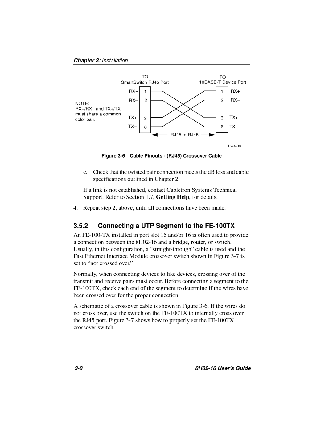
Figure 3-6 Cable Pinouts - (RJ45) Crossover Cable
c.Check that the twisted pair connection meets the dB loss and cable specifications outlined in Chapter 2.
If a link is not established, contact Cabletron Systems Technical Support. Refer to Section 1.7, Getting Help, for details.
4.Repeat step 2, above, until all connections have been made.
3.5.2Connecting a UTP Segment to the FE-100TX
An
Normally, when connecting devices to like devices, crossing over of the transmit and receive pairs must occur. Before connecting a segment to the
A schematic of a crossover cable is shown in Figure
|