Appendix C: Optional Installations and Mode Switch Bank Settings
C.4 INSTALLING OPTIONAL FAST ETHERNET INTERFACE MODULES
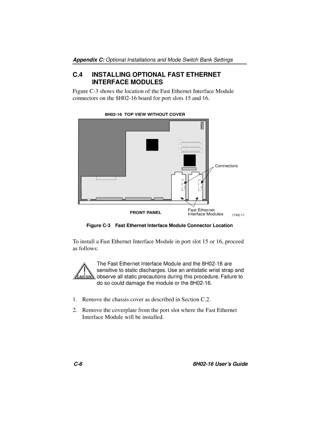
Figure C-3 shows the location of the Fast Ethernet Interface Module connectors on the 8H02-16 board for port slots 15 and 16.
Connectors
FRONT PANEL | Fast Ethernet | |
Interface Modules | ||
|
Figure C-3 Fast Ethernet Interface Module Connector Location
To install a Fast Ethernet Interface Module in port slot 15 or 16, proceed as follows:
The Fast Ethernet Interface Module and the
!sensitive to static discharges. Use an antistatic wrist strap and
C AUT IO N observe all static precautions during this procedure. Failure to do so could damage the module or the
1.Remove the chassis cover as described in Section C.2.
2.Remove the coverplate from the port slot where the Fast Ethernet Interface Module will be installed.
|
