|
|
| |
|
|
|
|
Normal | Sequence Note |
| Failure Symptoms At This Part Of The |
Sequence |
|
| Sequence |
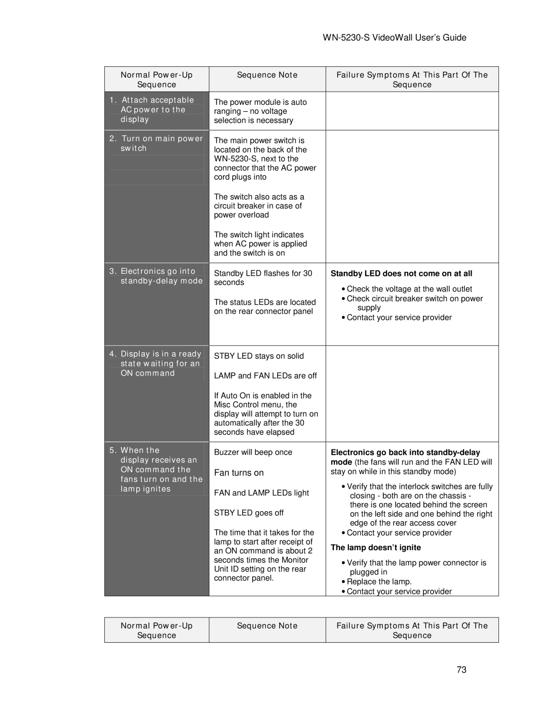
1. Attach acceptable | The power module is auto |
|
|
AC power to the | ranging – no voltage |
|
|
display | selection is necessary |
|
|
|
|
|
|
2. Turn on main power | The main power switch is |
|
|
switch | located on the back of the |
|
|
|
|
| |
| connector that the AC power |
|
|
| cord plugs into |
|
|
| The switch also acts as a |
|
|
| circuit breaker in case of |
|
|
| power overload |
|
|
| The switch light indicates |
|
|
| when AC power is applied |
|
|
| and the switch is on |
|
|
|
|
|
|
3. Electronics go into | Standby LED flashes for 30 |
| Standby LED does not come on at all |
| seconds |
| • Check the voltage at the wall outlet |
|
|
| |
| The status LEDs are located |
| • Check circuit breaker switch on power |
|
| supply | |
| on the rear connector panel |
| |
|
| • Contact your service provider | |
|
|
| |
|
|
|
|
4. Display is in a ready | STBY LED stays on solid |
|
|
state waiting for an |
|
|
|
ON command | LAMP and FAN LEDs are off |
|
|
|
|
| |
| If Auto On is enabled in the |
|
|
| Misc Control menu, the |
|
|
| display will attempt to turn on |
|
|
| automatically after the 30 |
|
|
| seconds have elapsed |
|
|
|
|
|
|
5. When the | Buzzer will beep once |
| Electronics go back into |
display receives an |
|
| mode (the fans will run and the FAN LED will |
ON command the | Fan turns on |
| stay on while in this standby mode) |
fans turn on and the |
|
| • Verify that the interlock switches are fully |
lamp ignites | FAN and LAMP LEDs light |
| |
|
| closing - both are on the chassis - | |
| STBY LED goes off |
| there is one located behind the screen |
|
| on the left side and one behind the right | |
| The time that it takes for the |
| edge of the rear access cover |
|
| • Contact your service provider | |
| lamp to start after receipt of |
| The lamp doesn’t ignite |
| an ON command is about 2 |
| |
| seconds times the Monitor |
| • Verify that the lamp power connector is |
| Unit ID setting on the rear |
| |
|
| plugged in | |
| connector panel. |
| |
|
| • Replace the lamp. | |
|
|
| |
|
|
| • Contact your service provider |
Normal
Sequence
Sequence Note
Failure Symptoms At This Part Of The
Sequence
73
