WN-5230-S VideoWall User’s Guide
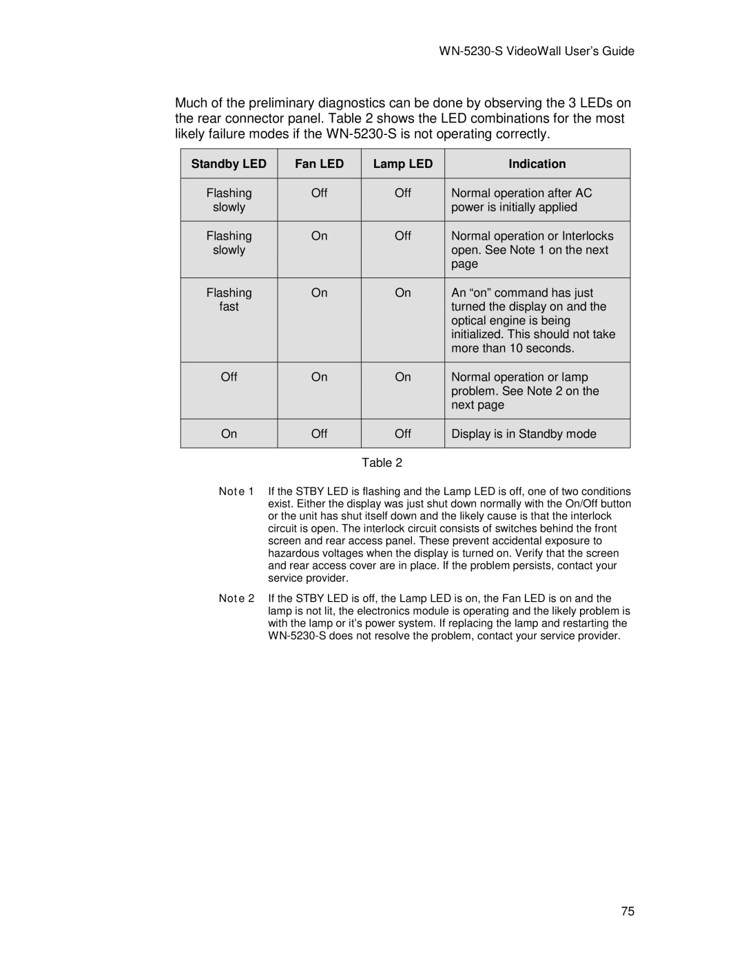
Much of the preliminary diagnostics can be done by observing the 3 LEDs on the rear connector panel. Table 2 shows the LED combinations for the most likely failure modes if the
Standby LED | Fan LED | Lamp LED | Indication |
|
|
|
|
Flashing | Off | Off | Normal operation after AC |
slowly |
|
| power is initially applied |
|
|
|
|
Flashing | On | Off | Normal operation or Interlocks |
slowly |
|
| open. See Note 1 on the next |
|
|
| page |
|
|
|
|
Flashing | On | On | An “on” command has just |
fast |
|
| turned the display on and the |
|
|
| optical engine is being |
|
|
| initialized. This should not take |
|
|
| more than 10 seconds. |
|
|
|
|
Off | On | On | Normal operation or lamp |
|
|
| problem. See Note 2 on the |
|
|
| next page |
|
|
|
|
On | Off | Off | Display is in Standby mode |
|
|
|
|
|
| Table 2 |
|
Note 1 If the STBY LED is flashing and the Lamp LED is off, one of two conditions exist. Either the display was just shut down normally with the On/Off button or the unit has shut itself down and the likely cause is that the interlock circuit is open. The interlock circuit consists of switches behind the front screen and rear access panel. These prevent accidental exposure to hazardous voltages when the display is turned on. Verify that the screen and rear access cover are in place. If the problem persists, contact your service provider.
Note 2 If the STBY LED is off, the Lamp LED is on, the Fan LED is on and the lamp is not lit, the electronics module is operating and the likely problem is with the lamp or it’s power system. If replacing the lamp and restarting the
75
