WN-5230-S VideoWall User’s Guide
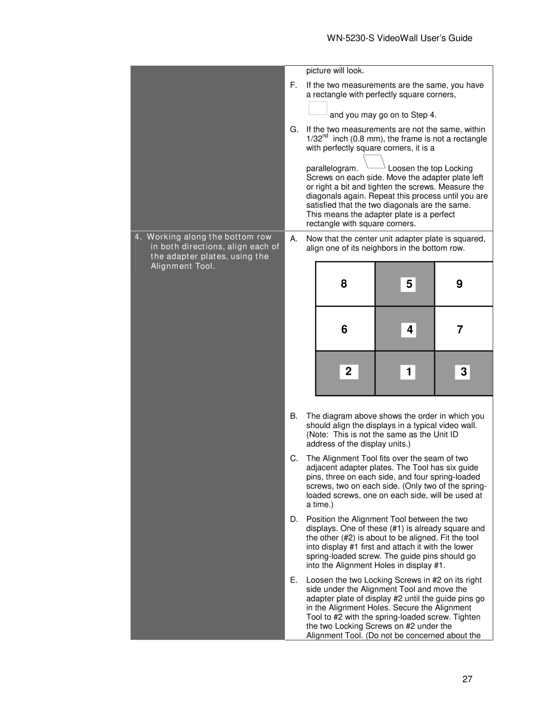
4.Working along the bottom row in both directions, align each of the adapter plates, using the Alignment Tool.
picture will look.
F.If the two measurements are the same, you have a rectangle with perfectly square corners,
![]()
![]() and you may go on to Step 4.
and you may go on to Step 4.
G.If the two measurements are not the same, within 1/32nd inch (0.8 mm), the frame is not a rectangle with perfectly square corners, it is a
parallelogram. ![]() Loosen the top Locking Screws on each side. Move the adapter plate left or right a bit and tighten the screws. Measure the diagonals again. Repeat this process until you are satisfied that the two diagonals are the same. This means the adapter plate is a perfect rectangle with square corners.
Loosen the top Locking Screws on each side. Move the adapter plate left or right a bit and tighten the screws. Measure the diagonals again. Repeat this process until you are satisfied that the two diagonals are the same. This means the adapter plate is a perfect rectangle with square corners.
A.Now that the center unit adapter plate is squared, align one of its neighbors in the bottom row.
|
|
|
|
|
|
|
|
|
|
|
|
|
|
| 8 |
|
|
| 5 |
|
| 9 |
|
| |||
|
|
|
|
|
|
|
|
|
|
|
|
|
|
|
|
|
|
|
|
|
|
|
|
|
|
| |
6 |
|
|
|
|
|
| |||||||
4 | 7 |
|
| ||||||||||
|
|
|
|
|
|
|
|
|
|
|
|
|
|
|
|
|
|
|
|
|
|
|
| ||||
2 |
|
| 1 |
|
| 3 |
| ||||||
|
|
|
|
|
|
|
|
|
|
|
|
|
|
B.The diagram above shows the order in which you should align the displays in a typical video wall. (Note: This is not the same as the Unit ID address of the display units.)
C.The Alignment Tool fits over the seam of two adjacent adapter plates. The Tool has six guide pins, three on each side, and four
D.Position the Alignment Tool between the two displays. One of these (#1) is already square and the other (#2) is about to be aligned. Fit the tool into display #1 first and attach it with the lower
E.Loosen the two Locking Screws in #2 on its right side under the Alignment Tool and move the adapter plate of display #2 until the guide pins go in the Alignment Holes. Secure the Alignment Tool to #2 with the
27