WN-5230-S VideoWall User’s Guide
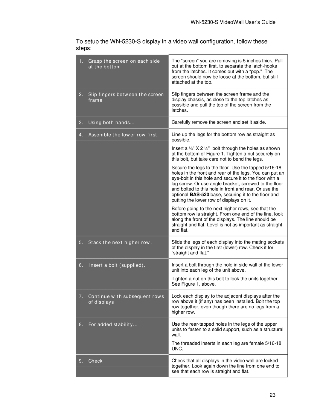
To setup the
1.Grasp the screen on each side at the bottom
The “screen” you are removing is 5 inches thick. Pull out at the bottom first, to separate the
2.Slip fingers between the screen frame
Slip fingers between the screen frame and the display chassis, as close to the top latches as possible and pull the top of the screen from the latches.
3. Using both hands… | Carefully remove the screen and set it aside. |
|
|
4.Assemble the lower row first. Line up the legs for the bottom row as straight as
possible.
Insert a ¼” X 2 ½” bolt through the holes as shown at the bottom of Figure 1. Tighten a nut securely on this bolt, but take care not to bend the legs.
Secure the legs to the floor. Use the tapped
Before going to the next higher rows, see that the bottom row is straight. From one end of the line, look along the front of the displays. The line should be straight and flat. Level is not as important as straight and flat.
5.Stack the next higher row. Slide the legs of each display into the mating sockets of the display in the first (lower) row. Check it for “straight and flat.”
6.Insert a bolt (supplied).
7.Continue with subsequent rows of displays
Insert a bolt through the hole in side wall of the lower unit into each leg of the unit above.
Tighten a nut on this bolt to lock the units together. See Figure 1, above.
Lock each display to the adjacent displays after the row above it (if any) has been installed. Bolt the top row together, even though there are no legs from a higher row.
8. | For added stability… | Use the |
|
| units to fasten to a solid support, such as a structural |
|
| wall. |
|
| The threaded inserts in each leg are female |
|
| UNC. |
|
|
|
9. | Check | Check that all displays in the video wall are locked |
|
| together. Look again down the line from one end to |
|
| see that each row is straight and flat. |
|
|
|
23
