TruCluster Server
Page
Contents
1.2.1
Setting Up the Memory Channel Cluster Interconnect
Using Fibre Channel Storage
2.2
Configuring a Shared Scsi Bus for Tape Drive Use
10.1
11.1
13.3.2
Worldwide ID-to-Disk Name Conversion Table Index Examples
10-2
Figures
Contents
Xiv Contents
Tables
10-4
Audience
Organization
Related Documents
About This Manual
Xx About This Manual
About This Manual
Reader’s Comments
Conventions
Cluster
Page
Introduction
TruCluster Server Product
Disks Needed for Installation
Memory Requirements
Minimum Disk Requirements
1.1 Tru64 Unix Operating System Disk
Member Boot Disk
Clusterwide Disks
Generic Two-Node Cluster
Quorum Disk
Member System
Growing a Cluster from Minimum Storage to a Nspof Cluster
Introduction
Minimum Two-Node Cluster with UltraSCSI BA356 Storage Unit
Introduction
Two-Node Cluster with Two UltraSCSI DS-BA356 Storage Units
Introduction
12Introduction
Memory
Creating a Nspof Cluster
Nspof Cluster Using HSZ70s in Multiple-Bus Failover Mode
Kgpsa
Introduction
Page
Hardware Requirements and Restrictions
TruCluster Server Member System Requirements
PCI Backplane Slot Layout
Memory Channel Restrictions
4Hardware Requirements and Restrictions
Host Bus Adapter Restrictions
Fibre Channel Requirements and Restrictions
6Hardware Requirements and Restrictions
Hardware Requirements and Restrictions
KZPSA-BB Scsi Adapter Restrictions
RAID Array Controller Restrictions
Disk Device Restrictions
KZPBA-CB Scsi Bus Adapter Restrictions
RAID Controller Minimum Required Array Controller Software
Scsi Signal Converters
RAID Controller Scsi IDs
DS-DWZZH-03 and DS-DWZZH-05 UltraSCSI Hubs
Scsi Cables
Cable Connector Pins Configuration Use Density
Supported Scsi Cables
Scsi Terminators and Trilink Connectors
Supported Scsi Terminators and Trilink Connectors
Page
Shared Scsi Bus Configuration Requirements
Scsi Bus Performance
Scsi Bus Versus Scsi Bus Segments
Transmission Methods
KZPBA-CB KZPSA-BB
Scsi Bus Device Identification Numbers
Data Path
Bus Speed
Scsi Bus Speeds
Scsi Bus Length
Scsi Bus Segment Length
Terminating the Shared Scsi Bus When Using UltraSCSI Hubs
Using a Dwzzh UltraSCSI Hub in a Cluster Configuration
UltraSCSI Hubs
DS-DWZZH-03 Description
Shows a front view of the DS-DWZZH-03 UltraSCSI hub
DS-DWZZH-05 Configuration Guidelines
DS-DWZZH-05 Description
DS-DWZZH UltraSCSI Hub Maximum Configurations
DS-DWZZH-03 DS-DWZZH-05
DS-DWZZH-05 Fair Arbitration
DS-DWZZH-05 Address Configurations
DS-DWZZH-05 Rear View
DS-DWZZH-05 Indicators
Scsi Bus Termination Power
Installing the DS-DWZZH-05 UltraSCSI Hub
Preparing the UltraSCSI Storage Configuration
Page
Page
Page
KZPBA-CB ID 6 T
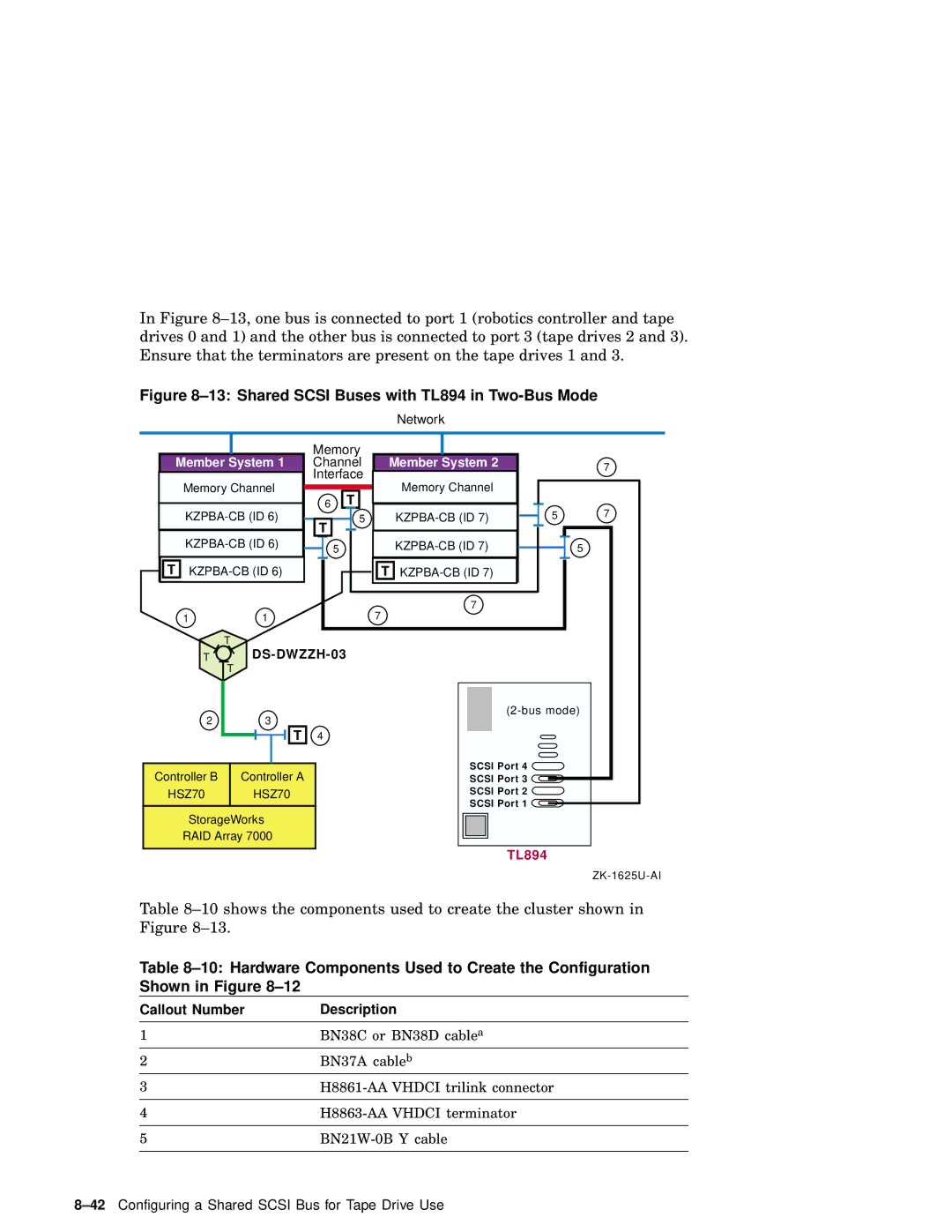
Callout Number Description
Page
Page
KZPBA-CB ID DS-DWZZH-03
HSZ80
Page
Page
Planning Your TruCluster Server Hardware Configuration
Planning Your Configuration
To increase You can
Obtaining the Firmware Release Notes
TruCluster Server Hardware Installation
Configuring TruCluster Server Hardware
Step Action Refer to
Configuring TruCluster Server Hardware
Page
Cluster Administration
Displaying KZPBA-CB Adapters with the show Console Commands
Example 4-1 Displaying Configuration on an AlphaServer DS20
TIG
Example 4-2 Displaying Devices on an AlphaServer DS20
P00 show device
Example 4-3 Displaying Configuration on an AlphaServer
Example 4-4 Displaying Devices on an AlphaServer
Displaying Console Environment Variables and Setting
Example 4-4 Displaying Devices on an AlphaServer 8200
P00show pk
P00show isp
Example 4-7 Setting the KZPBA-CB Scsi Bus ID
Setting the KZPBA-CB Scsi ID
KZPBA-CB Termination Resistors
JA1
Setting Up the Memory Channel Cluster Interconnect
MC1 and MC1.5 Jumper Configuration
Setting the Memory Channel Adapter Jumpers
1 MC1 and MC1.5 Jumpers
2 MC2 Jumpers
MC2 Jumper Configuration
Jumper Description Example
MC2 Linecard Jumper Configurations
JumperDescriptionExample
Installing the Memory Channel Adapter
Installing the MC2 Optical Converter in the Member System
Installing the Memory Channel Cables
Installing the Memory Channel Hub
Installing the MC1 or MC1.5 Cables
Connecting MC1 or MC1.5 Link Cables in Virtual Hub Mode
Connecting MC1 Link Cables in Standard Hub Mode
Installing the MC2 Cables
Connecting Memory Channel Adapters to Hubs
10Setting Up the Memory Channel Cluster Interconnect
Running Memory Channel Diagnostics
12Setting Up the Memory Channel Cluster Interconnect
Example 5-1 Running the mccable Test
Mccable
Upgrading Memory Channel Adapters
MC1
If adding a Memory Channel interconnect Install
Standard Hub Configuration
18Setting Up the Memory Channel Cluster Interconnect
Dbx p rmadapters1-rmpprailva-rmcsize
MC1 to MC2 Virtual Hub Rolling Upgrade
MC1 Hub AlphaServer
MC2 MC1
MC2 Hub
AlphaServer Member System MC2 Hub
Opto opto 1/opto only
MC1 to MC2 Standard Hub Rolling Upgrade Final Configuration
Using Fibre Channel Storage
Procedure for Installation Using Fibre Channel Disks
Using Fibre Channel Storage
Fibre Channel Overview
Basic Fibre Channel Terminology
Frame
Fibre Channel Topologies
Point-to-Point
Point-to-Point Topology
Fabric
Fabric Topology
Arbitrated Loop Topology
Hub
10Using Fibre Channel Storage
Using Fibre Channel Storage
Multiple-Bus Nspof Configuration Number
Fibre Channel Switch HSG Controller a Port
Zoning and Cascaded Switches
Zoning
Cascaded Switches
A Simple Zoned Configuration
Installing and Configuring Fibre Channel Hardware
Installing and Setting Up the Fibre Channel Switch
Installing the Switch
Managing the Fibre Channel Switches
Using the Switch Front Panel
Press Enter. You can change your mind and not reboot
Admin ipAddrSet
Logging In to the Switch with a Telnet Connection
Telnet Session Default User Names for Fibre Channel Switches
Setting the Switch Name via Telnet Session
Installing the Kgpsa PCI-to-Fibre Channel Adapter Module
Setting the KGPSA-BC or KGPSA-CA to Run on a Fabric
P00 set mode diag
P00 wwidmgr -set adapter -item 9999 -topo fabric
You can use the wwidmgr -show adapter command as follows
Obtaining the Worldwide Names of Kgpsa Adapters
28Using Fibre Channel Storage
Set this Cacheups
Use the command set failover copy =
Example 6-1 Determine HSG80 Connection Names
HSG80 show connection
HSG80 rename !NEWCON49 peppga1
Obtaining the Worldwide Names of HSG80 Controller
34Using Fibre Channel Storage
Using Fibre Channel Storage
Before You Install
Configure the HSG80 Storagesets
Example 6-2 Setting Up the Mirrorset
HSG80 RUN Config
38Using Fibre Channel Storage
Using Fibre Channel Storage
Adding Units and Identifiers to the HSG80 Storagesets
HSG80 show d131
42Using Fibre Channel Storage
Converting Storageset Unit Numbers to Disk Names
Set the Device Unit Number
P00 wwidmgr -clear all P00 show wwid
P00 wwidmgr -show wwid
46Using Fibre Channel Storage
P00 wwidmgr -quickset -udid
Displaying the Available Boot Devices
P00 show wwid
Example 6-6 Sample Fibre Channel Device Names
P00 show dev
You are now ready to install the Tru64 Unix operating system
Install the Tru64 Unix Operating System
Determining /dev/disk/dskn to Use for a Cluster Installation
# hwmgr -view dev grep Identifier grep
Reset the bootdefdev Console Environment Variable
Label the Disks to Be Used to Create the Cluster
54Using Fibre Channel Storage
Add Additional Systems to the Cluster
P00 set bootdefdev dga132.1002.0.1.0
Using Fibre Channel Storage
Overview
HSG80 SET Nofailover HSG80 SET Multibusfailover COPY=THIS
60Using Fibre Channel Storage
Initialize the console
# /usr/sbin/emxmgr -m emx0
# emxmgr -t emx1
64Using Fibre Channel Storage
Using the emxmgr Utility Interactively
# emxmgr
66Using Fibre Channel Storage
Overview
Hardware Requirements for a Hard Partition in a Cluster
Riser BN39B I/O Riser Cable
CD-ROM
Page
Front View of Expansion and Primary PCI Drawers
Expansion PCI Drawer
Page
Page
COM1PRINTEN1 HPCOUNT2 HPQBBMASK03
HPQBBMASK5 HPQBBMASK6 HPQBBMASK7 Srommask
Example 7-2 Turning Partition Power On
Page
Determining AlphaServer GS80/160/320 System Configuration
Example 7-3 Displaying AlphaServer GS160 System Information
Page
Example 7-4 Displaying Console Serial Bus Information
CPU3/SROM
Updating AlphaServer GS80/160/320 Firmware
Updating GS80/160/320 Firmware
Remove all hardware partitions
P00 boot dqa0
Set the hard partitions back to the original configuration
Page
Configuring a Shared Scsi Bus for Tape Drive Use
Preparing the TZ88 for Shared Bus Usage
Setting the TZ88N-VA Scsi ID
TZ88N-VA Scsi ID Switches
TZ88N-VA Switch Settings
Cabling the TZ88N-VA
Shared Scsi Buses with SBB Tape Drives
Setting the TZ88N-TA Scsi ID
Cabling the TZ88N-TA
Setting the DS-TZ89N-VW Scsi ID
Preparing the TZ89 for Shared Scsi Usage
DS-TZ89N-VW Scsi ID Switches
DS-TZ89N-VW Switch Settings
Cabling the DS-TZ89N-VW Tape Drives
Setting the DS-TZ89N-TA Scsi ID
Cabling the DS-TZ89N-TA Tape Drives
Setting the Compaq 20/40 GB DLT Tape Drive Scsi ID
Compaq 20/40 GB DLT Tape Drive
Cabling the Compaq 20/40 GB DLT Tape Drive
Compaq 20/40 GB DLT Tape Drive Rear Panel
12Configuring a Shared Scsi Bus for Tape Drive Use
H885-AA trilink connector
Setting the Compaq 40/80-GB DLT Drive Scsi ID
Compaq 40/80-GB DLT Drive
Cabling the Compaq 40/80-GB DLT Drive
Hardware Components in the Configuration in Figure
Cabling a Shared Scsi Bus with a Compaq 40/80-GB DLT Drive
Hardware Components in the Configuration in -6
Setting the TZ885 Scsi ID
Preparing the TZ885 for Shared Scsi Usage
Cabling the TZ885 Tape Drive
Cabling a Shared Scsi Bus with a TZ885
Setting the TZ887 Scsi ID
Preparing the TZ887 for Shared Scsi Bus Usage
Cabling the TZ887 Tape Drive
TZ887 DLT MiniLibrary Rear Panel
Cabling a Shared Scsi Bus with a TZ887
Setting the TL891 or TL892 Scsi ID
24Configuring a Shared Scsi Bus for Tape Drive Use
Cabling the TL891 or TL892 MiniLibraries
26Configuring a Shared Scsi Bus for Tape Drive Use
Configuring a Shared Scsi Bus for Tape Drive Use
28Configuring a Shared Scsi Bus for Tape Drive Use
1 TL890 DLT MiniLibrary Expansion Unit Hardware
Preparing the TL890 DLT MiniLibrary Expansion Unit
Preparing the DLT MiniLibraries for Shared Scsi Bus Usage
Cabling the DLT MiniLibraries
Configuring a Shared Scsi Bus for Tape Drive Use
11 TL890 and TL892 DLT MiniLibraries on Shared Scsi Buses
Configuring a Base Module as a Slave
328215-00X, BN21K, or BN21L cable c
Powering Up the DLT MiniLibrary
Setting the TL890/TL891/TL892 Scsi ID
36Configuring a Shared Scsi Bus for Tape Drive Use
TL894 Default Scsi ID Settings
Setting TL894 Robotics Controller and Tape Drive Scsi IDs
1 TL894 Robotic Controller Required Firmware
38Configuring a Shared Scsi Bus for Tape Drive Use
3 TL894 Tape Library Internal Cabling
12 TL894 Tape Library Four-Bus Configuration
Connecting the TL894 Tape Library to the Shared Scsi Bus
13 Shared Scsi Buses with TL894 in Two-Bus Mode
H879-AA terminator
11 TL895 Default Scsi ID Settings
Setting the TL895 Tape Library Scsi IDs
10.1 TL895 Robotic Controller Required Firmware
10.3 TL895 Tape Library Internal Cabling
46Configuring a Shared Scsi Bus for Tape Drive Use
Upgrading a TL895
14 TL895 Tape Library Internal Cabling
Connecting the TL895 Tape Library to the Shared Scsi Bus
Configuring a Shared Scsi Bus for Tape Drive Use
12 MUC Switch Functions
MUC Switch Functions
Communications with the Host Computer
Setting the MUC Scsi ID
14 TL893 Default Scsi IDs
Tape Drive Scsi IDs
13 MUC Scsi ID Selection
15 TL896 Default Scsi IDs
11.5 TL893 and TL896 Automated Tape Library Internal Cabling
15 TL893 Three-Bus Configuration
16 TL896 Six-Bus Configuration
Configuring a Shared Scsi Bus for Tape Drive Use
17 Shared Scsi Buses with TL896 in Three-Bus Mode
12.1 TL881 and TL891 DLT MiniLibraries Overview
12.1.1 TL881 and TL891 DLT MiniLibrary Tabletop Model
12.1.2 TL881 and TL891 MiniLibrary Rackmount Components
12.1.3 TL881 and TL891 Rackmount Scalability
DLT MiniLibrary Part Numbers
18 DLT MiniLibrary Part Numbers
18 DLT MiniLibrary Part Numbers
Setting the Standalone MiniLibrary Tape Drive Scsi ID
Cabling the TL881 or TL891 DLT MiniLibrary
64Configuring a Shared Scsi Bus for Tape Drive Use
Configuring a Shared Scsi Bus for Tape Drive Use
18 TL891 Standalone Cluster Configuration
Cabling the Rackmount TL881 or TL891 DLT MiniLibrary
68Configuring a Shared Scsi Bus for Tape Drive Use
19 TL891 DLT MiniLibrary Rackmount Configuration
Configuring a Base Unit as a Slave to the Expansion Unit
Powering Up the TL881/TL891 DLT MiniLibrary
72Configuring a Shared Scsi Bus for Tape Drive Use
Compaq ESL9326D Enterprise Library
General Overview
13.2 ESL9326D Enterprise Library Overview
Library Electronics and Tape Drive Scsi IDs
13.3.3 ESL9326D Enterprise Library Internal Cabling
Scsi ID
Library electronics a
78Configuring a Shared Scsi Bus for Tape Drive Use
Page
Using Scsi Bus Signal Converters
Types of Scsi Bus Signal Converters
Using the Scsi Bus Signal Converters
Dwzza and Dwzzb Signal Converter Termination
Standalone Scsi Signal Converter
DS-BA35X-DA Termination
DS-BA35X-DA Personality Module Switches
Terminating the Shared Scsi Bus
Page
BN21W-0B Y Cable
HD68 Trilink Connector H885-AA
Overview of Disk Storage Shelves
1 BA350 Storage Shelf
2 BA356 Storage Shelf
Non-UltraSCSI BA356 Storage Shelf
Page
BA356 Internal Scsi Bus
BA356 Jumper and Terminator Module Identification Pins
UltraSCSI BA356 Storage Shelf
Page
Preparing a BA350 Storage Shelf for Shared Scsi Usage
Preparing a BA356 Storage Shelf for Shared Scsi Usage
Connecting Storage Shelves Together
Connecting a BA350 and a BA356 for Shared Scsi Bus Usage
BA350 and BA356 Cabled for Shared Scsi Bus Usage
Connecting Two BA356s for Shared Scsi Bus Usage
10 Two BA356s Cabled for Shared Scsi Bus Usage
Connecting Two UltraSCSI BA356s for Shared Scsi Bus Usage
11 Two UltraSCSI BA356s Cabled for Shared Scsi Bus Usage
Hardware Components Used for Configuration Shown in Figure
BN37A cable a
Page
KZPSA-BB ID HSZ50
BN21K or BN21L cablea b
Cabling an HSZ20 in a Cluster Using External Termination
Page
Hardware Components Used in Configuration Shown in Figure
BN21K or BN21L cableb
Hub
Page
Page
Step Action Refer to
Page
PCI-to-SCSI Storage
Kzpsa PCI-to-SCSI
Installing a KZPSA-BB or KZPBA-CB Using External Termination
Power down the member system. Install
Step Action Refer to
Example 10-1 Displaying Configuration on an AlphaServer
P00 show config
Example 10-1 Displaying Configuration on an AlphaServer 4100
Example 10-2 Displaying Devices on an AlphaServer
Example 10-2 Displaying Devices on an AlphaServer 4100
Example 10-3 Displaying Configuration on an AlphaServer
Example 10-4 Displaying Devices on an AlphaServer
P00show pk
Qlogic ISP1020 devices KZPBA-CBs as isp0 and isp1 with disks
P00 show isp
Example 10-8 Setting the KZPBA-CB Scsi Bus ID
Example 10-9 Setting KZPSA-BB Scsi Bus ID and Speed
KZPSA-BB and KZPBA-CB Termination Resistors
Updating the KZPSA-BB Adapter Firmware
UPD update pkb0
Page
Worldwide ID-to-Disk Name Conversion Table
Table A-1 Converting Storageset Unit Numbers to Disk Names
Page
Index
Init, 6-25, 6-48, 6-50, 6-55
TZ887
Use, 6-62
10-19 SRM console, 4-7t, 7-4, 10-5t Srom TL894 TL895
Hwmgr
LFU, 10-18 booting, 10-18 starting, 10-18 updating firmware
Setting, 6-30
See subscriber connector SCM
MUC
KZPBA-CB, 4-9t, 10-4t, 10-7t KZPSA, 10-4t, 10-7t
DWZZA, 2-11 upgrading
How to Order Tru64 Unix Documentation
Name Order Number
Page
Reader’s Comments
Spit Brook RD Nashua NH