Manuals
/
Compaq
/
Computer Equipment
/
Printer
Compaq
P5000 Series
setup guide
Select a Site, Pedestal Model Dimensions
Models:
P5000 Series
1
19
186
186
Download
186 pages
31.97 Kb
16
17
18
19
20
21
22
23
Specs
Environmental Characteristics
Install
Ribbon Path Diagram Location
Prime Signal
Error Handling
Dimension
Configuring the Printer
Diagnosing Problems
Built-in Diagnostic Tools
Page 19
Image 19
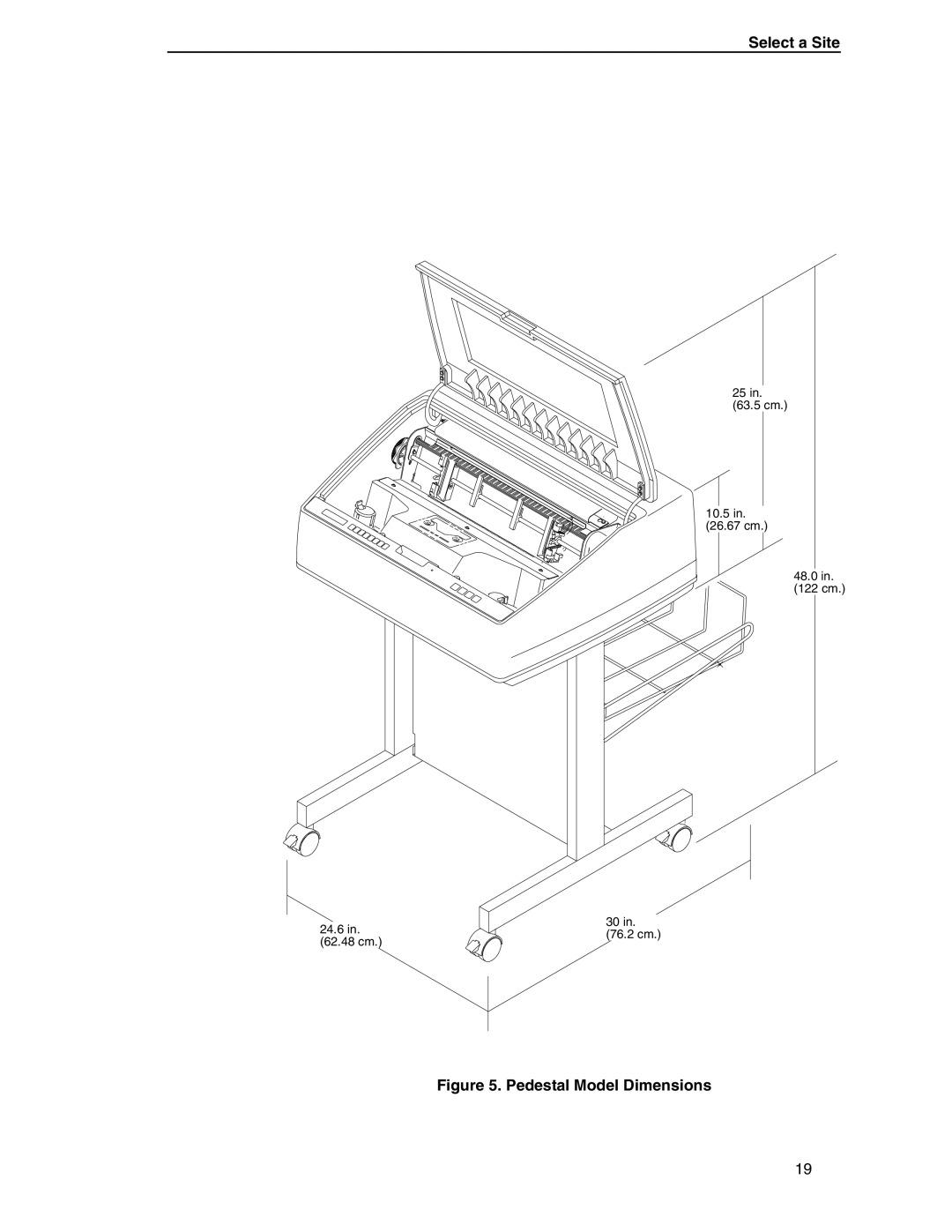
Select a Site
25 in.
(63.5 cm.)
10.5 in.
(26.67 cm.)
48.0 in.
(122 cm.)
30 in.
24.6 in.
(76.2 cm.)
(62.48 cm.)
Figure 5. Pedestal Model Dimensions
19
Page 18
Page 20
Page 19
Image 19
Page 18
Page 20
Contents
Setup Guide
Page
Printronix P5000 series with DEC LG Emulation
Trademark Acknowledgments
Trademark Acknowledgments
Table of Contents
Table of Contents
Configuring the Printer
Interfaces
Standard Ascii Character Set
Printing Conventions in This Guide
About This Guide
Related Documents
P5000 series with DEC LG Emulation
P5000 series with DEC LG Emulation Printer Family
DEC LG Emulation Model Number Print Speed Pedestal Cabinet
Host Computer Interfaces
Printer Emulations
Printer Emulations
DEC LG Emulation Printers
Output Control
LinePrinter Plus Features
Graphics Enhancement Option
Taking Care of Your Printer
Protocols and Emulations
Built-in Diagnostic Tools
Graphics and Vertical Formatting
Line Matrix Printing
Line Matrix Printing
Printing Speed
Before You Begin
Power Requirements
Select a Site
Interface Connections Interface Type Maximum Cable Length
Before You Begin
Select a Site
Pedestal Model Dimensions
Component Locations
Printer Component Locations
Remove the Cardboard Packing
Remove the Shipping Restraints Cabinet Model
Remove the Cardboard Packing
Remove the Shipping Restraints Cabinet Model
Remove the Hammer Bank Protective Foam and Foam Strips
Remove the Platen Protective Foam
Remove the Platen Protective Foam
Adjusting Paper Supports
Adjust the Paper Supports
Release the Paper Chains
Release the Paper Chains
Remove Tag and Tie Wrap from Fence or Passive Paper Stacker
Remove the Tags
Attach the Control Panel Overlays
Remove the Shipping Restraints Pedestal Model
Attach the Control Panel Overlays
Remove the Shipping Restraints Pedestal Model
Remove the Hammer Bank Protective Foam
Removing Platen Protective Foam
Adjust the Paper Supports
Remove Tag
Remove Tag
Attaching the Output Basket
Attach the Output Basket
Attaching Control Panel Overlays
Connect the Interface and Power Cables
Install Basic Components
Install Basic Components
Interface and Power Locations
Connect the Interface and Power Cables
Ribbon Path Diagram Location
Install the Ribbon
Forms Thickness Lever
Install the Ribbon
Ribbon Path
Left Ribbon Hub
Forms Thickness Lever and Tractor Doors
Load the Paper
Paper Slot Location
Load the Paper
Paper Scale
Horizontal Adjustment Knob
Power Switch
Power On the Printer
Set the Top-of-Form
Set the Top-of-Form
Raising the Forms Thickness Lever
Lowering the Forms Thickness Lever
Test the Printer
Printer Test Procedure Step Key Result
Overview
Configuring the Printer
Clear
Configuration Menu Overview
Default and Custom Configurations
Changing and Saving Parameter Settings
Changing and Saving Parameter Settings
Control Panels
Operating Modes
Unlocking and Locking the Enter Key
Factory Default Configuration Values
Unlocking and Locking the Enter Key
Maint / Misc
Example
Parameter Change Example Procedure Step Key Result
Changing Parameters
Example
To USE the Current Configuration Without Saving
Saving Your New Configuration
Saving Your New Configuration
Changing Parameters Saving Configurations Step Key Result
Deleting Your Configuration
Deleting Your Configuration
Changing Parameters Deleting Configurations Step Key Result
Printing the Current Configuration
Protecting Your Configurations
Protecting Your Configurations
Press until the desired option displays
Loading Configuration Values
Loading Configuration Values
Displays for about a second
Power-Up Configuration
Power-Up Configuration
Printer has selected
Configuration Main Menu
Configuration Menus
MAINT/MISC
DTR
Configuration Main Menu
CONFIG. Control
Load Config
Menu
Power-Up Config
Save Config
Print Config
Delete Config
Active Emulation
Active Emulation
Emulation
Submenu
Digital LG
Submenu
Font
Vert. Forms
Horiz. Forms
Unsolicited Rpt
Autowrap
CR Carriage Return
LF Line Feed
Plot Mode Opt
Print Mode Opt
5 Guard Bars
LinePrinter+
LinePrinter+
Font Attributes
Printer Protocol
Print Char Set
CPI/LPI Select
Slashed Zero
Proportional Spacing
Bold Print
Italic Print
Forms Length
Format
Margins
Perforation Skip
Define CR Code
Proprinter XL Emulation
Auto LF
Alternate Char Set
Define LF Code
FF Valid at TOF
Character Set
Ascii USA
Epson FX Emulation
Alternate Set 80-9F
Printer Select
Epson FX Emulation
Series
Series Emulation
Overstrike
Control Code
Series Emulation
Alt. Set 80-9F
Sfcc d Command
Select Sfcc
Evfu Select
IGP/PGL Emulation
IGP/PGL Emulation
Define CR Code Carriage Return
Define LF Code Line Feed
PI Slew Range
Auto Uppercase
CR Edit
Select Font
Select LPI
UPC Descenders
Skip Command Prefix
Power On IGP/PGL
Extended Execute Copy
Optimized Ratio
Ignore Mode
Ignore Character
IGP100 Compatbl
IGP/VGL Emulation
IGP/VGL Emulation
Sfcc & Pwrup
Power Up
Graphics Options
Rot. Char Size
Submenu True Vert 1/10
Absorb after PY
UPC Descenders
Allowed
IGP/VGL Emulation Dark Barcode
Width Limit
Width Limit Height Max. Width
Error Handling
Ignore ch#2
Ignore / DB8 Setup
Ignore Chars
Ignore ch#1
Host PI
Font Set
PI Control
Printer PI
Maint / Misc
Hex Dump Mode
Power-Up State
Display Language
Host Interface
Host Interface
Serial Submenu
Interface Type
Data Protocol
Parity
Baud Rate
Word Length
Stop Bits
Request to Send
Data Terminal Ready
Buffer Size in K
Data Polarity
Parallel Submenu
Centronics Interface
Data Bit
Busy on Strobe
Prime Signal
Strobe Polarity
Response Polarity
PI Ignored
Dataproducts Submenu
Data Request Polarity
Bidirectional Submenu
Printer Control
Unidirectional
Power Saver Time
PMD Paper Motion Detection Fault
Slow Paper Slew
Printer Tests
Diagnostics
Paper Out Dots
Test Width
System Memory
Print Statistics
Ribbon Action
New Ribbon
Ribbonminder
Ribbon Adjust
Fault Action
Ribbon Size
Interfaces
Dataproducts Parallel Interface
Dataproducts Parallel Interface Signals
Dataproducts Parallel Interface
Dataproducts Parallel Interface Configuration
Dataproducts Parallel Interface Configuration
Centronics Parallel Interface
Centronics Interface Signals
Centronics Parallel Interface
Centronics Parallel Interface Configuration
Centronics Parallel Interface Configuration
Terminating Resistor Configurations
Terminating Resistor Configurations
Removal and Installation
Removal and Installation
Ieee 1284 Parallel Interface
Compatibility Mode
Nibble Mode
Byte Mode
Signals
Negotiation Phase
Negotiation Phase
Page
Signals Type of Mode Pin Source of Data Compatible
RS-232 and RS-422 Serial Interfaces
RS-232 and RS-422 Serial Interfaces
RS-232
RS-232 and RS-422 Serial Interface Signals
RS-232 and RS-422 Serial Interface Error Handling
RS-232 and RS-422 Serial Interface Protocol
RS-232 and RS-422
RS-232 and RS-422 Serial Interface Configuration
RS-232 only
Interface Configuration
Interface Configuration
VMS Operating System
VMS Operating System
Exterior Cleaning
Cleaning Requirements
Interior Cleaning
Cleaning Requirements
Cleaning the Interior of the Printer
Interior Cleaning
Sample Print Test All E’s Step Key Result
Diagnosing Problems
Diagnosing Problems
Printer Self-Tests
Printer Self-Tests Sample Print Test All E’s Step Key Result
Hex Dump Sample
Printing a Hex Dump
Printing a Hex Dump Step Key Result
Fault Messages Requiring Field Service Attention
Fault Messages
23.5V PWR Fail
Access Null PTR
5V PWR Fail
15V PWR Fail
Exhaust FAN FLT
Firmware Error
Framing Error
HB not Installd
LO DRV. Short
Intake FAN Fault
Parity Error
ILL Inst Accss
Plat INV Parm
Power Saver Mode
Power Supply HOT
Plat INV CMD
Shuttle JAM
Software Error
Shutl INV CMD
Shutl INV Parm
148
Ribbon INK OUT Change Ribbon
Enable State Ribbon Life 100%
Configuration
Using the RibbonMinder
Using the RibbonMinder
Configuration RibbonMinder Configuration Step Key Result
Running a Job
New Ribbon Procedure Step Key Result
New Ribbon
Ribbon Action
Ribbon Action Configuration Step Key Result
Ribbon Action
RibbonMinder Fault
Ribbon Size
Ribbon Size Configuration Step Key Result
Ribbon Size
Fault Action
Ribbon Adjust
Labels
Ribbon Specifications
Paper Specifications
Paper
Environmental Characteristics
Printer Dimensions
Interfaces
Electrical Characteristics
Power Consumption
Operating Units Power Consumption Mode
Appendix a Printing Rates
Printing Rates
Standard Ascii Character Set
Appendix B
Internet
Sources of Support
Your Printronix Vendor
Your Application Vendor
Appendix C Sources of Support
Printronix Technical Support
Ascii
Glossary
Example Bold refers to a heavy or thick character
Appendix D
EIA/TIA
See also point
IGP
Ieee
Nvram
LCD
LED
NLQ
Pcba
OCR
ROM
RAM
VFU
Sfcc
OFF
174
Index
Coil HOT
177
LO DRV. Short *, 144
IGP/PGL
Page
Page
Ribbon INK OUT, Change Ribbon
Page
Page
Page
172292-001B
Top
Page
Image
Contents