Dell PowerEdge T710 Systems
April
Contents
Uefi Boot Settings Screen
Processor Settings Screen
Power Management Screen
Other Information You May Need
Entering the iDRAC Configuration Utility
Removing the Cooling Shroud Installing the Cooling Shroud
General Memory Module Installation
Installing a Hard Drive Into a
Installing an Optical or Tape Drive
Mode-Specific Guidelines Installing Memory Modules
Installing an Integrated Storage
Removing the Chassis Intrusion Switch
Installing the Chassis Intrusion Switch
Installing an Integrated Storage Controller
152
145
149
156
Troubleshooting Power Supplies 165
166
176
185
186
193
F11
Accessing System Features During Startup
Configurator documentation
See the BMC or iDRAC user documentation
Drives
Front-Panel Features and Indicators
USB connectors
Ports are USB 2.0-compliant
Perform a graceful shutdown before
Power button causes the system to
Power to the system is turned off
Seconds
LCD Panel Features
LCD Panel Features Buttons Description Left
Setup Menu
Home Screen
View Menu
Drive-status indicator green and amber About Your System
Hard-Drive Status Indicators
Drive-activity indicator green
Carrier
Time
Rebuild aborted
Seconds, and off six seconds About Your System
Back-Panel Features and Indicators
Back-Panel Features and Indicators About Your System
Supports one full-height, full-length
Power supply
Wide card in slots
30.99-cm 12.2-in, x16 wide card
Serial connector
Guidelines for Connecting External Devices
Video connector
Security cable slot Connects a cable lock to the system
NIC Indicator Codes
Power Indicator Codes
LCD Status Messages
Battery
Disabled, temp
Power cycle
Battery E1211 RAID
E122A
E122C CPU Power
Fault. Power
Cycle AC
Bios revision
E1410 Internal Error
Configuration. configuration
Error. Power
Power supply E1614 Power Supply #
Check error
E1610 Power Supply #
### W error
E1624 Lost power
E1620 Power Supply #
Power error
E1626 Power Supply
E1714 Unknown error
Error on Bus
Error on Slot
E1711 PCI parity
E1810 Hard drive ##
Fault. Review
E1920 iDRAC6 Upgrade
Clear SEL E1812 Hard drive ##
Unusable Check DIMMs E2013 Bios unable to
Configuration
Configured but
Failure. Power
E2018 Programmable
Timer error
E2019 Parity error
E201A SuperIO
E201E Post memory
POST. Check Screen Message E2023 Bios Unable to
E201D Shutdown test
Test failure
##. Power
E2110 Multibit Error
Disabled on
On Dimm ##
Config. provide
Errors
I1920 iDRAC6 Upgrade
I1911 LCD Log Full
Solving Problems Described by LCD Status Messages
Removing LCD Status Messages
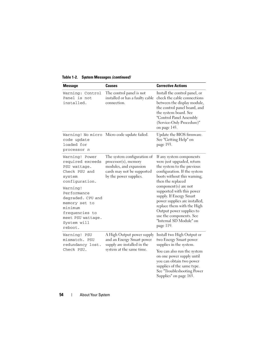
System Messages
Alert! iDRAC6 not
Rebooting
Power required
Responding
Memory disabled
Alert! Power
System boot
Fatal error
System board Please run Setup
Mode detected
Is installed on
CPU x installed
Different cache
Bootable media is
CPUs with
Sizes detected
Correct Connectors Gate A20 failure
Configuration on
Error
Each CPU should
Disabled
Accessible USB
Disabled. If
Keyboard fuse has
Memory set to
Mirror mode
Installed Pairs. Pairs must Be matched in size and geometry
Memory tests
Error Expected
No boot device
No timer tick
Available
Quad rank Dimm
Read fault Requested sector not found
Plug & Play
Detected after
Seek operation
Seek error
Sector not found
Shutdown failure
Following DIMMs should Match in size
Setup program
DIMMs should
Following DIMMs should
201
System memory See RAM
202
TCP/IP Transmission Control Protocol/Internet Protocol
203
204
Using Dell PowerEdge Diagnostics
205
Index
Hard drive
206
Accessing system features Power indicators, 12
207
208
Integrated storage controller card, 132
Keystroke
209
Memory options, 61, 63 serial communications options
210
211
212
213
214