System and Control Options
7.11.2Set Up Mapping for an Analog Sensor Input
•Use the arrows ↑↓ to choose Map Sensor To Relay from the Map Input/Sensor Menu, and press Enter ↵ .
•From the Select Sensor Menu, choose the input you
Map Sensor to Control Relay
•On the
To make changes to the mapping:
•If needed, press Enter ↵ to advance to the position directly below the relay.
•Use the arrows ↑↓ to choose Y (Yes - Mapped to this relay) or N (No - Not mapped), then press Enter ↵ .
•Press Enter ↵ to advance to the next position where you want to make a change.
•Use the arrows ↑↓ to choose Y (Yes - Mapped to this relay) or N (No - Not mapped), then press Enter ↵ .
•When finished, press Enter ↵ again.
Default Mappings - Analog Inputs to Control Relays
By default, analog inputs are not mapped to any control relay, as shown in Table 31.
Table 31 Default mapping of analog inputs to relays
Analog input | By default, mapped to control relay: |
|
|
Sensor_1 | (none) |
|
|
Sensor_2 | (none) |
|
|
Sensor_3 | (none) |
|
|
Sensor_4 | (none) |
|
|
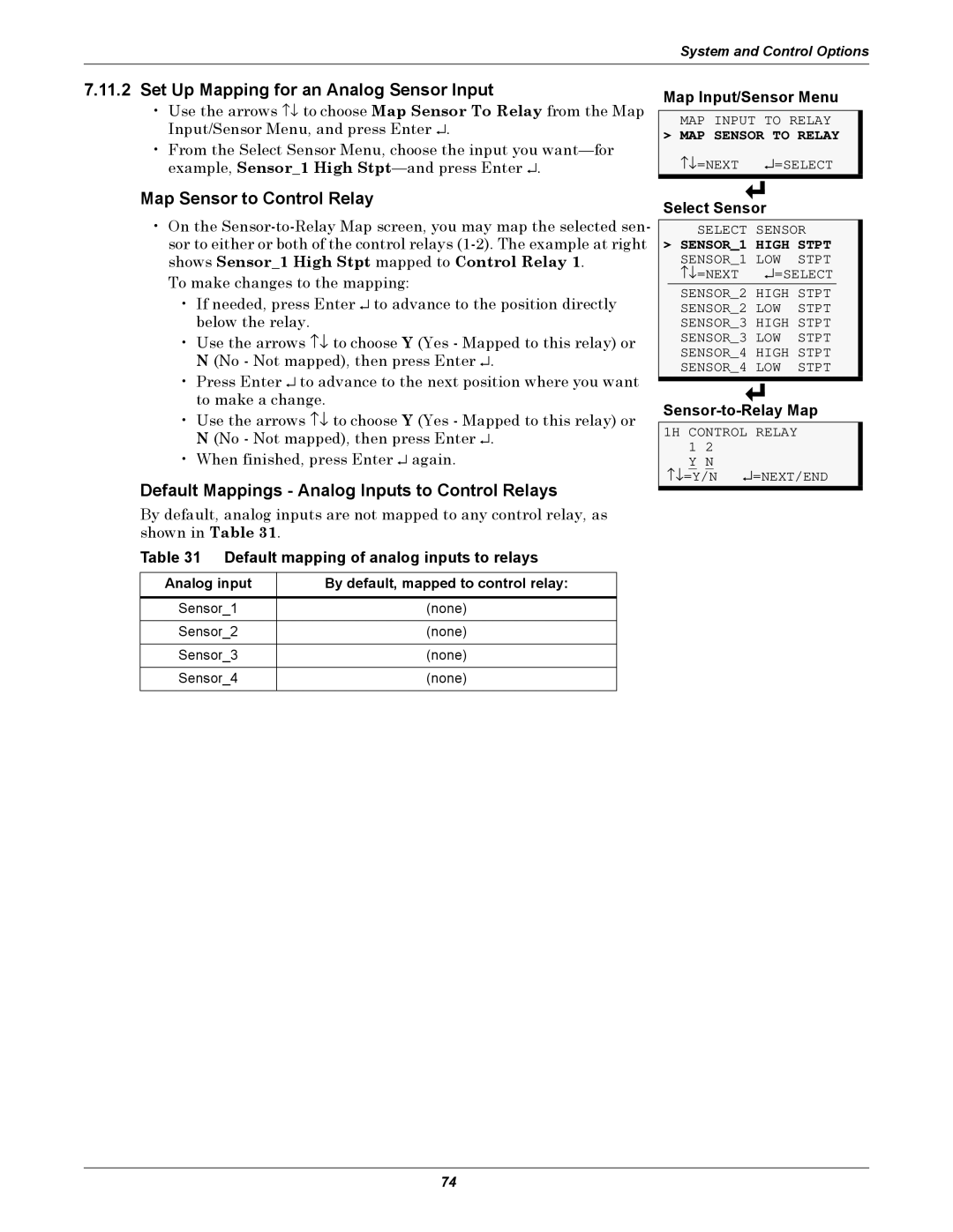
Map Input/Sensor Menu
MAP INPUT TO RELAY
> MAP SENSOR TO RELAY
↑↓ =NEXT ↵ =SELECT
Select Sensor
SELECT SENSOR
> SENSOR_1 HIGH STPT
SENSOR_1 LOW STPT | |
↑↓ =NEXT | ↵ =SELECT |
SENSOR_2 HIGH STPT SENSOR_2 LOW STPT SENSOR_3 HIGH STPT SENSOR_3 LOW STPT SENSOR_4 HIGH STPT SENSOR_4 LOW STPT
1H CONTROL RELAY
1 2 Y N
↑↓ =Y/N ↵ =NEXT/END
74