Wiring and Connections
3.2.2 | Connecting Digital Outputs | ON | PF |
|
| |
| To connect a digital output: |
|
| RELAY | ||
| 1. Turn OFF electrical power to the AC8. |
|
| OUTPUTS | ||
|
|
|
| (BOTTOM) | ||
| 2. | If necessary, remove a conduit knockout to |
|
| (TOP) |
|
|
|
| 4 | 8 | ||
|
| permit wire entry into the AC8 enclosure. |
|
|
| |
|
|
|
|
| 7 | |
| 3. Bring the wire(s) into the AC8 enclosure |
|
| 3 | ||
|
|
|
| |||
|
|
|
|
|
| |
|
| through a conduit knockout or access slot. |
|
| 2 | 6 |
| 4. | Loosen the appropriate screw and slip the | ON OFF |
|
| |
| PFM2 | 1 | 5 | |||
|
| stripped end of the wire into the terminal | ON OFF |
|
| |
|
| PFM5 |
|
| ||
|
| block. |
|
| ||
|
|
| REV | (TOP) | ||
| 5. Tighten the screw until it holds the wire |
|
|
| (BOTTOM) | |
|
|
|
| 8 | ||
|
| snugly. |
|
| 4 | |
|
|
|
|
| ||
| ! | CAUTION |
|
| 2 | 7 |
|
|
| 6 | |||
|
|
|
|
| 3 |
|
|
| To reduce the risk of fire or electric |
|
|
| 5 |
|
| shock, do not interconnect the outputs |
|
| 1 | |
|
|
|
|
| ||
|
| of different Class 2 circuits. |
|
| TB2: | |
|
|
|
|
| ||
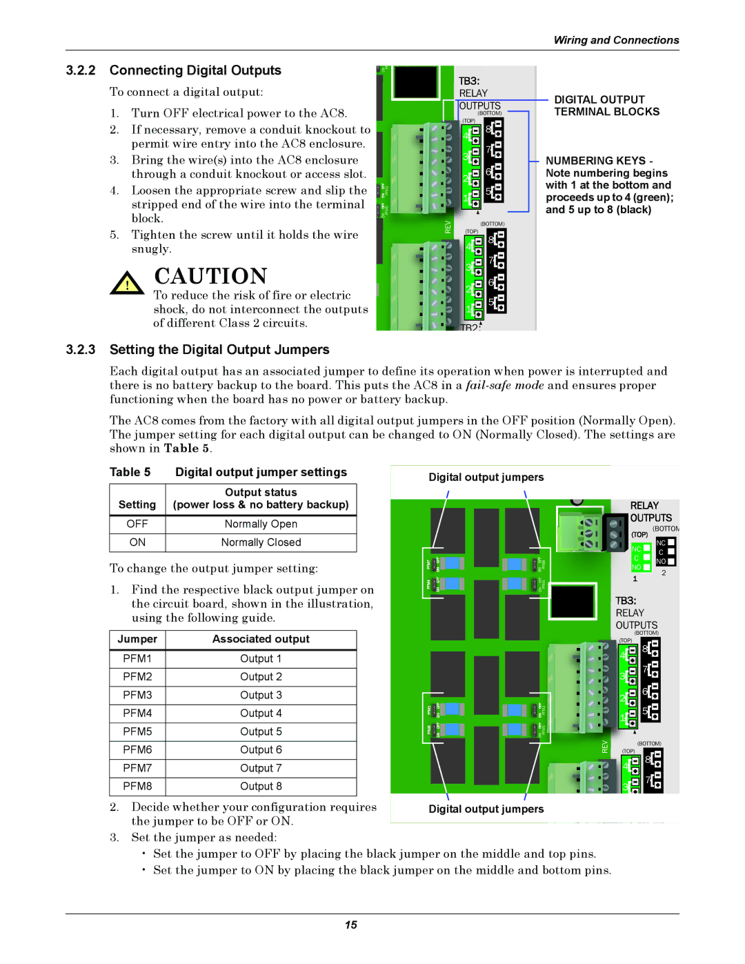
DIGITAL OUTPUT TERMINAL BLOCKS
NUMBERING KEYS - Note numbering begins with 1 at the bottom and proceeds up to 4 (green); and 5 up to 8 (black)
3.2.3Setting the Digital Output Jumpers
Each digital output has an associated jumper to define its operation when power is interrupted and there is no battery backup to the board. This puts the AC8 in a
The AC8 comes from the factory with all digital output jumpers in the OFF position (Normally Open). The jumper setting for each digital output can be changed to ON (Normally Closed). The settings are shown in Table 5.
Table 5 | Digital output jumper settings |
|
|
| Output status |
Setting | (power loss & no battery backup) |
OFF | Normally Open |
|
|
ON | Normally Closed |
|
|
To change the output jumper setting:
1.Find the respective black output jumper on the circuit board, shown in the illustration, using the following guide.
Jumper | Associated output |
Digital output jumpers | TB4: | ||
|
|
|
|
|
|
|
|
|
|
|
|
(BOTTOM |
|
| NC | NC | |
|
| C | ||
|
| C | ||
ON OFF | PFM8 | NO | ||
NO | ||||
2 | ||||
ON OFF |
|
| ||
PFM3 |
|
|
RELAY
OUTPUTS
(BOTTOM)
PFM1 | Output 1 |
PFM2 | Output 2 |
|
|
PFM3 | Output 3 |
|
|
PFM4 | Output 4 |
|
|
PFM5 | Output 5 |
|
|
PFM6 | Output 6 |
|
|
PFM7 | Output 7 |
|
|
PFM8 | Output 8 |
ON OFF | PFM2 |
ON OFF | PFM5 |
REV
(TOP)
![]()
![]() 8
8![]()
![]() 4
4![]()
![]()
![]()
![]()
![]()
![]() 7
7![]()
![]() 3
3![]()
![]()
![]()
![]()
![]()
![]() 6
6![]()
![]() 2
2![]()
![]()
![]()
![]()
![]()
![]() 5
5![]()
![]() 1
1![]()
![]()
![]()
![]()
(BOTTOM)
(TOP)
![]()
![]() 8
8![]()
![]() 4
4![]()
![]()
![]()
![]()
![]()
![]() 7
7![]()
![]() 3
3![]()
![]()
![]()
![]()
2. Decide whether your configuration requires |
|
|
|
|
|
|
|
|
|
| 6 | |
Digital o | utpu | t | jum | pe | rs | 2 | ||||||
|
|
|
| |||||||||
|
|
|
| |||||||||
the jumper to be OFF or ON. |
|
|
|
|
|
|
|
|
|
| 5 | |
|
|
|
|
|
|
|
|
|
| |||
|
|
|
|
|
|
|
|
| ||||
|
|
|
|
|
|
|
|
|
|
3.Set the jumper as needed:
•Set the jumper to OFF by placing the black jumper on the middle and top pins.
•Set the jumper to ON by placing the black jumper on the middle and bottom pins.
15