Introduction
1.9Typical Sequence
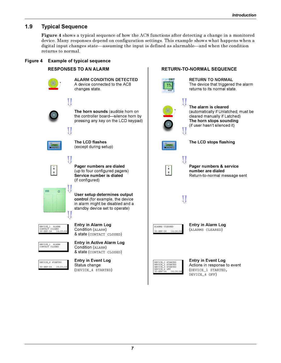
Figure 4 shows a typical sequence of how the AC8 functions after detecting a change in a monitored device. Many responses depend on configuration settings. This example shows what happens when a digital input changes state—assuming the input is defined as alarmable—and when the condition returns to normal.
Figure 4 Example of typical sequence
RESPONSES TO AN ALARM
ALARM CONDITION DETECTED A device connected to the AC8 changes state.
The horn sounds (audible horn on the controller
RETURN-TO-NORMAL SEQUENCE
RETURN TO NORMAL
The device that triggered the alarm returns to its normal state.
![]() The alarm is cleared (automatically if Unlatched; must be cleared manually if Latched)
The alarm is cleared (automatically if Unlatched; must be cleared manually if Latched)
The horn stops sounding
(if user hasn’t silenced it)
ESC
DEVICE_1 ALARM
CONTACT CLOSED
DEVICE_1 ALARM
CONTACT CLOSED
DEVICE_4 STARTED
The LCD flashes
(except during setup)
Pager numbers are dialed
(up to four configured pagers)
Service number is dialed (if configured)
User setup determines output control (for example, the device in alarm might be disabled and a standby device set to operate)
Entry in Alarm Log
Condition (ALARM)
&state (CONTACT CLOSED)
Entry in Active Alarm Log
Condition (ALARM)
&state (CONTACT CLOSED)
Entry in Event Log
Status change
(DEVICE_4 STARTED)
ESC
ALARMS CLEARED
DEVICE_1 STARTED DEVICE_2 STARTED DEVICE_3 STARTED DEVICE_4 OFF
The LCD stops flashing
Pager numbers & service number are dialed
Entry in Alarm Log
(ALARMS CLEARED)
Entry in Event Log Actions in response to event
(DEVICE_1 STARTED, DEVICE_4 OFF)
7