System and Control Options
7.11Setup System - Setup I/O Matrix
The Setup I/O Matrix menu allows you to configure the AC8’s digital and analog inputs to trigger var- ious actions in either or both of the two control relays. Each relay can be set up to respond to more than one digital or analog input.
Almost any mapping combination can be used. For example, you may decide to trigger an action in Control Relay 1 when Device_1 goes into alarm, or you might want to generate an action in Control Relay 2 when Sensor_1 High Setpoint goes into alarm.
To set up the mapping of inputs to relays:
Log In and Choose Setup System
• From the Main Menu, use the arrows ↑↓ to choose System and Control, then press Enter ↵ (see 7.1 - Login for help).
• Enter your password at the Login screen.
• From the System and Control Menu, use the arrows ↑↓ to choose Setup System, then press Enter ↵ .
Select Setup I/O Matrix
• From the Setup System Menu, shown at right, use the arrows ↑↓ to choose Setup I/O Matrix and press Enter ↵ .
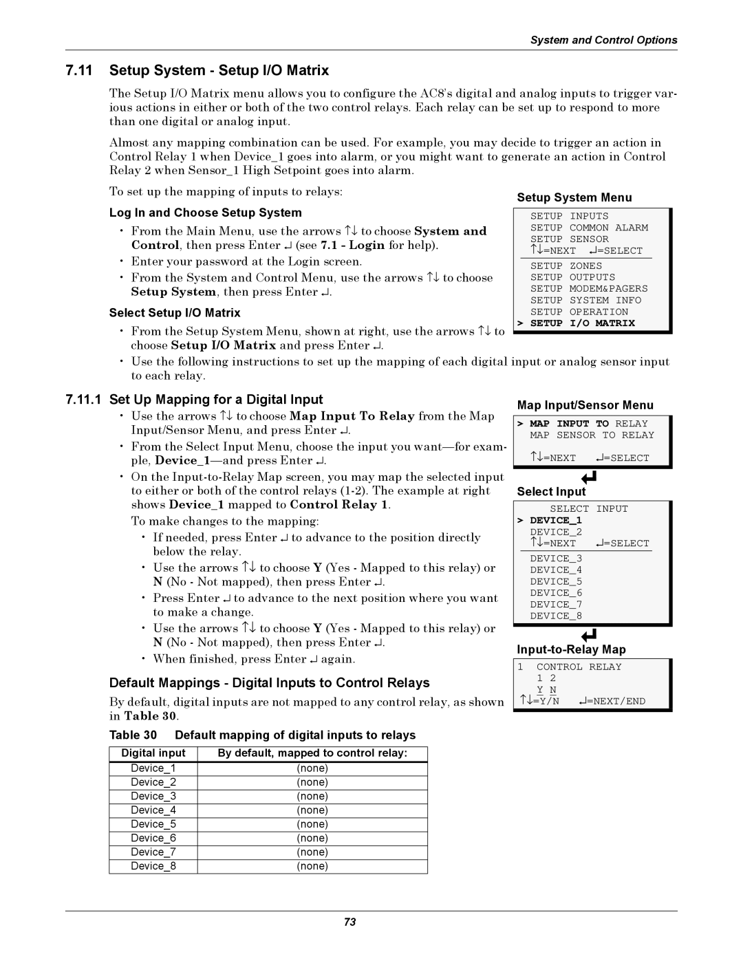
Setup System Menu
SETUP INPUTS SETUP COMMON ALARM SETUP SENSOR
↑↓ =NEXT ↵ =SELECT
SETUP ZONES SETUP OUTPUTS SETUP MODEM&PAGERS SETUP SYSTEM INFO SETUP OPERATION
> SETUP I/O MATRIX
•Use the following instructions to set up the mapping of each digital input or analog sensor input to each relay.
7.11.1Set Up Mapping for a Digital Input
•Use the arrows ↑↓ to choose Map Input To Relay from the Map Input/Sensor Menu, and press Enter ↵ .
•From the Select Input Menu, choose the input you
•On the
To make changes to the mapping:
•If needed, press Enter ↵ to advance to the position directly below the relay.
•Use the arrows ↑↓ to choose Y (Yes - Mapped to this relay) or N (No - Not mapped), then press Enter ↵ .
•Press Enter ↵ to advance to the next position where you want to make a change.
•Use the arrows ↑↓ to choose Y (Yes - Mapped to this relay) or N (No - Not mapped), then press Enter ↵ .
•When finished, press Enter ↵ again.
Default Mappings - Digital Inputs to Control Relays
By default, digital inputs are not mapped to any control relay, as shown in Table 30.
Table 30 Default mapping of digital inputs to relays
Digital input | By default, mapped to control relay: |
Device_1 | (none) |
Device_2 | (none) |
Device_3 | (none) |
Device_4 | (none) |
Device_5 | (none) |
Device_6 | (none) |
Device_7 | (none) |
Device_8 | (none) |
Map Input/Sensor Menu
>MAP INPUT TO RELAY MAP SENSOR TO RELAY
↑↓ =NEXT ↵ =SELECT
Select Input
SELECT INPUT
> DEVICE_1 |
| |
| DEVICE_2 | ↵ =SELECT |
| ↑↓ =NEXT | |
|
|
|
| DEVICE_3 |
|
| DEVICE_4 |
|
| DEVICE_5 |
|
| DEVICE_6 |
|
| DEVICE_7 |
|
| DEVICE_8 |
|
1 CONTROL RELAY
1 2 Y N
↑↓ =Y/N ↵ =NEXT/END
73