Introduction
1.6Typical Configuration
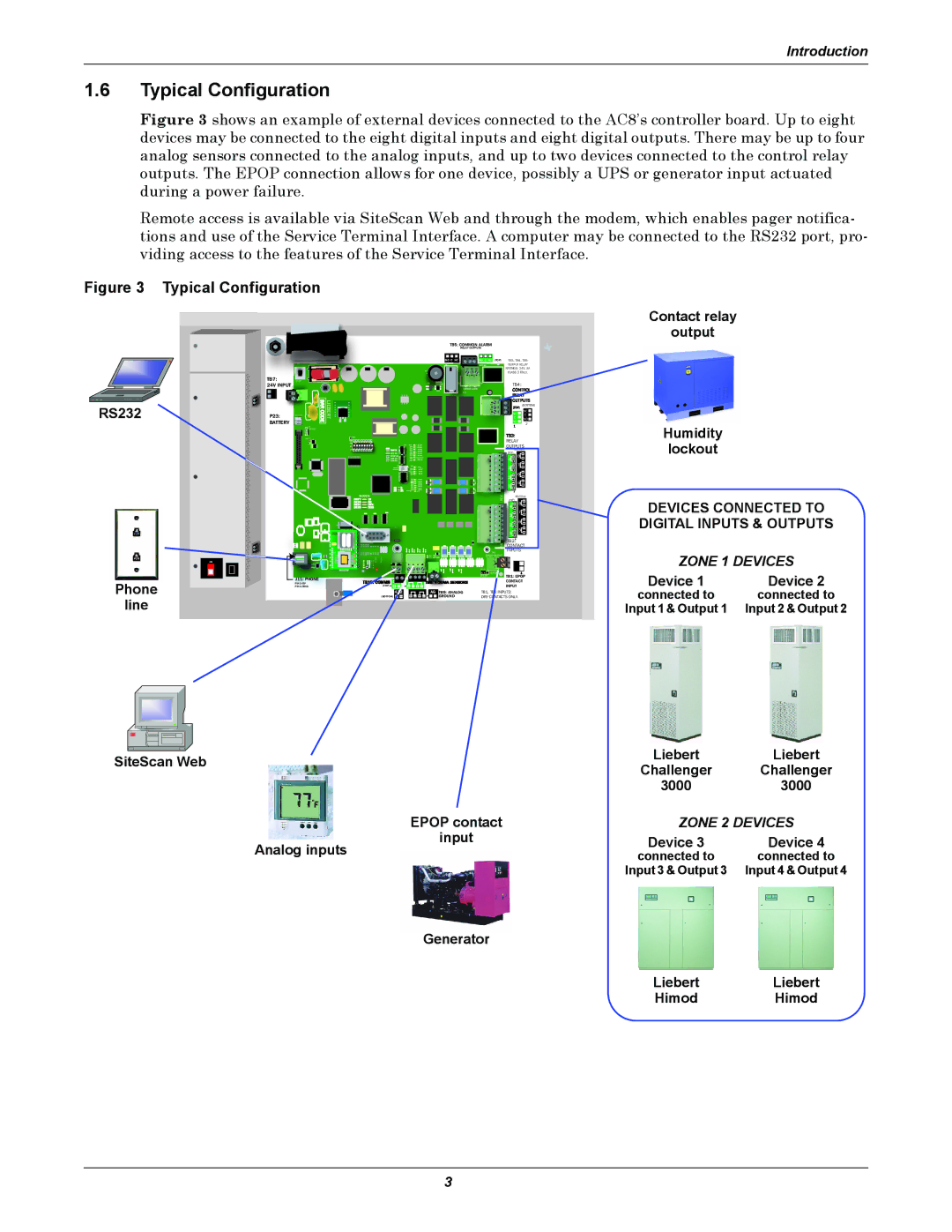
Figure 3 shows an example of external devices connected to the AC8’s controller board. Up to eight devices may be connected to the eight digital inputs and eight digital outputs. There may be up to four analog sensors connected to the analog inputs, and up to two devices connected to the control relay outputs. The EPOP connection allows for one device, possibly a UPS or generator input actuated during a power failure.
Remote access is available via SiteScan Web and through the modem, which enables pager notifica- tions and use of the Service Terminal Interface. A computer may be connected to the RS232 port, pro- viding access to the features of the Service Terminal Interface.
Figure 3 | Typical Configuration |
|
|
|
|
|
|
|
|
| ||
|
|
|
|
|
|
|
| TB5: COMMON ALARM |
|
|
| |
|
|
|
|
|
|
|
| RELAY OUTPUTS |
|
|
| |
|
|
|
|
|
|
|
| NO C NC | NO C NC | (TOP) | TB3, TB4, TB5 | |
|
|
|
|
|
|
|
|
| BOTTOM |
| OUTPUT RELAY | |
|
|
|
|
|
|
|
|
|
|
| RATINGS: 24V, 3A | |
|
|
|
|
|
|
| + |
|
|
| CLASS 2 ONLY. | |
| TB7: | START |
|
|
|
|
| ENABLE | TOP |
| TB4: |
|
| 24V INPUT |
|
|
|
|
|
| AUDIBLE |
|
| ||
RS232 |
|
| BARCODE | LIEBERT |
|
|
| Q11 |
|
|
|
|
|
|
|
|
|
|
|
| NO | NO | |||
|
|
|
|
|
|
|
|
|
|
|
| (BOTTOM) |
| P23: |
|
|
|
|
|
|
|
|
|
| NC |
|
|
|
|
|
|
|
|
|
| C | C | |
|
| BATTERY |
|
|
|
|
|
|
|
| NC | |
| BATTERY |
|
|
|
|
|
|
|
|
|
| 2 |
|
| LCD |
|
|
|
|
|
|
|
|
|
|
|
| CONTRAST |
|
|
|
|
|
|
|
|
|
|
|
| VBATT |
|
|
|
|
|
|
|
| RELAY |
|
|
|
|
|
|
|
|
|
|
|
|
| |
|
|
|
|
|
|
|
|
|
|
| OUTPUTS | |
|
|
|
|
|
|
|
|
|
|
| (BOTTOM) | |
|
|
|
|
|
|
|
|
|
|
| (TOP) |
|
|
|
|
|
| CAN TX |
|
|
|
|
| 8 |
|
|
|
|
|
| CAN RX |
|
|
|
|
| 4 |
|
|
|
|
|
|
|
|
|
|
|
| 7 |
|
|
|
|
|
|
|
|
|
|
|
| 3 |
|
|
|
|
|
|
|
|
|
|
|
| 6 |
|
|
|
|
|
|
|
|
|
|
|
| 2 |
|
|
|
|
|
|
|
|
| PFM2 |
|
| 5 |
|
|
|
|
|
|
|
|
|
|
|
| 1 |
|
|
|
|
|
|
|
|
| PFM5 |
|
|
|
|
|
|
|
| MODEM |
|
|
|
|
| REV | (BOTTOM) | |
|
|
|
|
|
|
|
|
|
| (TOP) |
| |
|
|
|
|
|
|
|
|
|
|
| 8 |
|
|
|
|
|
|
|
|
|
|
|
| 4 |
|
|
|
|
|
|
|
|
|
|
|
| 7 |
|
|
|
|
|
|
|
|
|
|
|
| 3 |
|
|
|
|
|
|
|
|
|
|
|
| 6 |
|
|
|
|
|
|
|
|
|
|
|
| 2 |
|
|
|
|
|
|
|
|
|
|
|
| 5 |
|
|
|
|
|
|
|
|
|
|
|
| 1 |
|
|
|
|
|
|
|
|
|
|
| ASS | TB2: |
|
|
|
|
|
|
|
|
|
|
| CONTACT | ||
|
|
|
|
|
|
|
|
|
| TB1 | INPUTS |
|
|
|
|
|
|
|
| EPOP INPUT |
|
| |||
|
|
|
|
|
|
|
|
|
|
| ||
| ON |
|
|
|
|
|
|
| EPOP |
|
| |
|
|
|
| MODEM |
|
|
|
| P19 |
|
|
|
|
|
|
|
|
|
|
|
| DIS EN |
| TB1: EPOP | |
|
| J11: PHONE |
|
|
|
|
|
|
|
| ||
Phone |
|
|
| 485 |
|
|
|
| CONTACT | |||
| PIN |
|
|
|
|
|
| |||||
| PIN |
| (TOP) | + — | + — + — |
|
|
| INPUT |
| ||
|
|
|
|
|
| AG | TB9: ANALOG | TB1, | INPUTS: |
| ||
|
|
| (BOTTOM) | — | + — + — | GROUND | DRY CONTACTS ONLY. |
| ||||
line |
|
|
|
|
|
|
|
|
|
|
|
|
Contact relay
output
Humidity
lockout
DEVICES CONNECTED TO DIGITAL INPUTS & OUTPUTS
ZONE 1 DEVICES
Device 1 | Device 2 |
connected to | connected to |
Input 1 & Output 1 | Input 2 & Output 2 |
|
|
| Liebert | Liebert | |
SiteScan Web | |||||
Challenger | Challenger | ||||
|
|
| |||
|
|
| 3000 | 3000 | |
|
| EPOP contact | ZONE 2 DEVICES | ||
|
| input | Device 3 | Device 4 | |
|
| Analog inputs | |||
|
| connected to | connected to | ||
|
|
| Input 3 & Output 3 | Input 4 & Output 4 | |
|
| Generator |
|
| |
|
|
| Liebert | Liebert | |
|
|
| Himod | Himod | |
3