Introduction
1.8LED Indicators
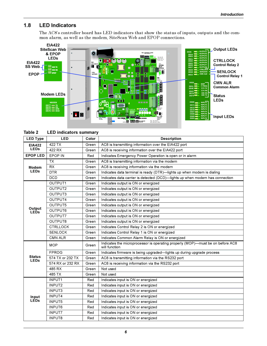
The AC8’s controller board has LED indicators that show the status of inputs, outputs and the com- mon alarm, as well as the modem, SiteScan Web and EPOP connections.
EIA422
SiteScan Web
& EPOP
LEDs
EIA422 |
| 24V INPUT |
|
SS Web |
| TB7: | START |
DS49 |
|
| |
| DS50 |
|
|
EPOP | DS68 | P23: | BATTERY |
|
| ||
|
| BATTERY |
|
BAR CODE
LCD
CONTRAST
LIEBERT
|
|
|
| DS56 | OUTPUT1 | Output LEDs |
TB5: COMMON ALARM |
|
|
| OUTPUT2 |
| |
| RELAY OUTPUTS |
|
| DS54 |
|
|
|
|
|
| OUTPUT3 |
| |
|
|
|
| DS63 |
| |
NO C NC | NO C NC | (TOP) | TB3, TB4, TB5 | OUTPUT4 |
| |
| BOTTOM |
| OUTPUT RELAY | DS61 | CTRLLOCK | |
ENABLE |
|
| RATINGS: 24V, 3A | OUTPUT5 | ||
+ |
|
| CLASS 2 ONLY. | DS60 |
| |
|
|
|
|
|
| |
AUDIBLE | TOP |
| TB4: | DS62 | OUTPUT6 | Control Relay 2 |
|
|
| OUTPUT7 | |||
Q11 |
|
|
| DS55 | ||
|
|
|
| DS57 | OUTPUT8 |
|
| (BOTTOM) | DS59 |
| CTRLLOCK |
|
| SENLOCK |
NO | NO |
|
|
|
|
| |
NC | NC | DS58 |
| SENLOCK |
|
|
|
C |
|
|
|
| |||
C |
|
| CMN ALR |
|
| Control Relay 1 | |
| 2 | DS53 |
|
|
| ||
|
|
|
|
|
| ||
|
|
|
|
|
|
|
Modem LEDs
MODEM
DS77![]() TX
TX
DS76 ![]() RX
RX
DS74 ![]() DTR
DTR
DS75![]() DCD
DCD
ON
MODEM
J11: PHONE
PIN
PIN
CAN TX
CAN RX
MODEM |
485
(TOP)![]() + —
+ — ![]() + — + —
+ — + —
|
|
| RELAY |
|
|
| |
|
|
| OUTPUTS |
|
| CMN ALR | |
|
|
| (BOTTOM) | DS52 |
| ||
|
|
| (TOP) |
|
| ||
|
|
|
| 8 | MOP | ||
|
|
| 4 |
| |||
|
|
|
|
| |||
|
|
| 3 | 7 | DS51 | F PROG | Common Alarm |
|
|
|
| ||||
|
|
| 2 | 6 | DS48 | 574 TX | |
|
|
| 1 | 5 | DS47 | 574 RX |
|
|
|
|
|
|
| ||
|
| REV |
|
| DS78 | 485 RX | Status |
|
|
| (BOTTOM) |
| 485 TX | ||
|
| (TOP) |
| DS79 | |||
|
|
|
| 8 |
| ||
|
|
| 4 |
|
|
| |
|
|
| 3 | 7 |
|
| LEDs |
|
|
|
|
|
| ||
|
|
| 2 | 6 | DS69 | INPUT1 | |
|
|
| 1 | 5 |
| INPUT2 |
|
|
|
|
| DS71 |
| ||
|
|
|
|
|
| ||
|
| ASS | TB2: | DS72 | INPUT3 |
| |
|
| CONTACT | INPUT4 |
| |||
|
| TB1 | INPUTS | DS70 |
| ||
TOP | EPOP INPUT |
|
| INPUT5 |
| ||
BOTTOM |
|
| DS67 |
| |||
|
| EPOP |
|
|
| ||
|
| P19 |
|
| DS66 | INPUT6 | Input LEDs |
|
| EPOP |
|
| DS65 | INPUT7 | |
|
| DIS EN | TB1: EPOP | ||||
|
|
| CONTACT | DS64 | INPUT8 | ||
|
|
| INPUT | ||||
| 422 |
|
| AG TB9: ANALOG | TB1, TB2 INPUTS: |
(BOTTOM) | + — |
| + — + — | GROUND | DRY CONTACTS ONLY. |
Table 2 | LED indicators summary |
| ||
LED Type | LED | Color | Description | |
EIA422 | 422 TX | Green | AC8 is transmitting information over the EIA422 port | |
LEDs | 422 RX | Green | AC8 is receiving information over the EIA422 port | |
EPOP LED | EPOP IN | Red | Indicates Emergency Power Operation is open or in alarm | |
| TX | Green | AC8 is transmitting information via the modem | |
Modem | RX | Green | AC8 is receiving information via the modem | |
LEDs | DTR | Green | Indicates data terminal is ready | |
| DCD | Green | Indicates data carrier is detected | |
| OUTPUT1 | Green | Indicates output is ON or energized | |
| OUTPUT2 | Green | Indicates output is ON or energized | |
| OUTPUT3 | Green | Indicates output is ON or energized | |
| OUTPUT4 | Green | Indicates output is ON or energized | |
Output | OUTPUT5 | Green | Indicates output is ON or energized | |
OUTPUT6 | Green | Indicates output is ON or energized | ||
LEDs | ||||
| OUTPUT7 | Green | Indicates output is ON or energized | |
| OUTPUT8 | Green | Indicates output is ON or energized | |
| CTRLLOCK | Green | Indicates Control Relay 2 is ON or energized | |
| SENLOCK | Green | Indicates Control Relay 1 is ON or energized | |
| CMN ALR | Green | Indicates Common Alarm Relay is ON or energized | |
| MOP | Green | Indicates the microprocessor is operating properly | |
| will function | |||
|
|
| ||
Status | FPROG | Green | Indicates firmware is being | |
574 TX or 232 TX | Green | AC8 is transmitting information via the RS232 port | ||
LEDs |
|
|
| |
574 RX or 232 RX | Green | AC8 is receiving information via the RS232 port | ||
| ||||
| 485 RX | Green | Not used | |
| 485 TX | Green | Not used | |
| INPUT1 | Red | Indicates input is ON or energized | |
| INPUT2 | Red | Indicates input is ON or energized | |
| INPUT3 | Red | Indicates input is ON or energized | |
Input | INPUT4 | Red | Indicates input is ON or energized | |
LEDs | INPUT5 | Red | Indicates input is ON or energized | |
| INPUT6 | Red | Indicates input is ON or energized | |
| INPUT7 | Red | Indicates input is ON or energized | |
| INPUT8 | Red | Indicates input is ON or energized | |
6