Introduction
1.5Outside Enclosure Overview
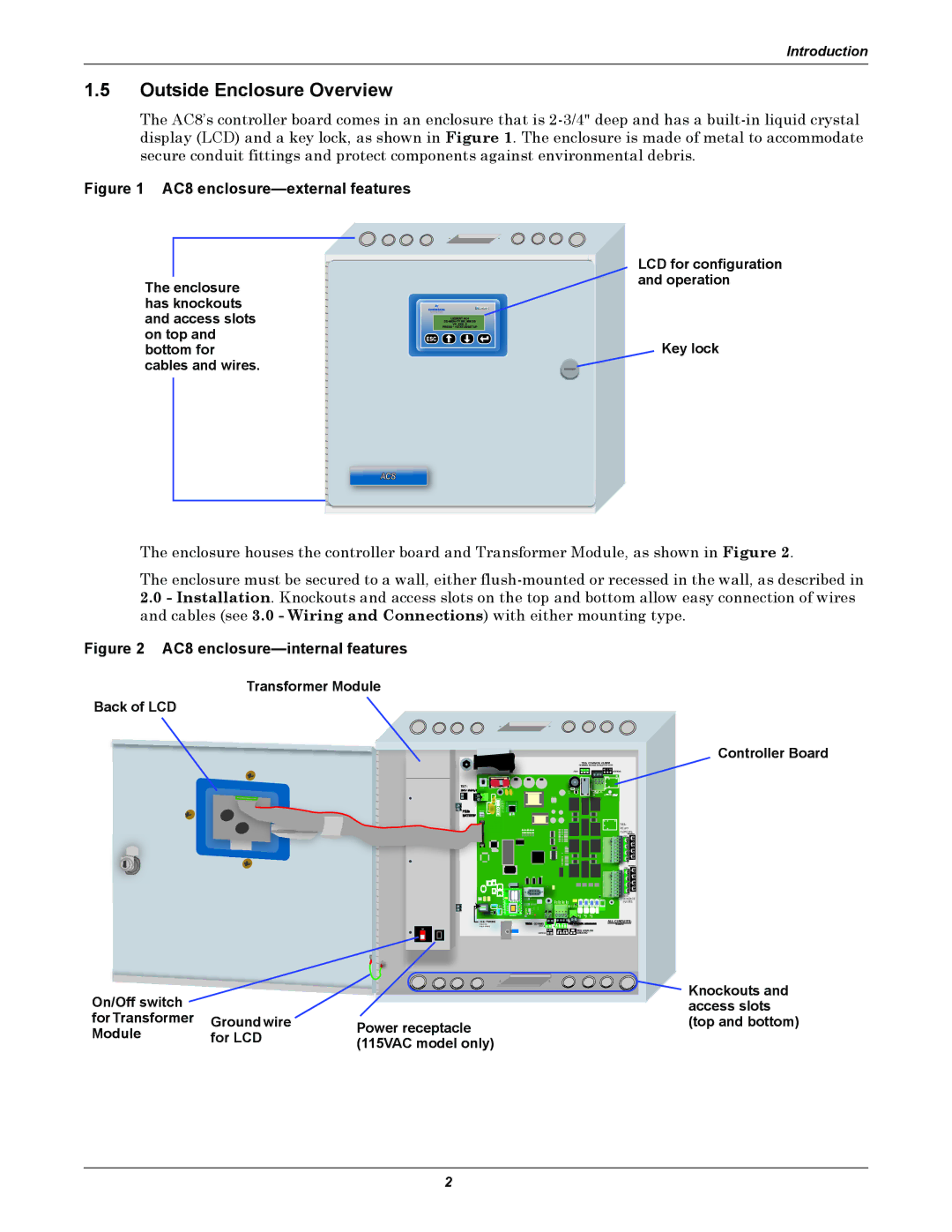
The AC8’s controller board comes in an enclosure that is
Figure 1 AC8 enclosure—external features
|
|
|
|
|
|
| LCD for configuration |
|
|
|
|
|
|
| and operation |
The enclosure |
| ||||||
|
| ||||||
has knockouts |
|
|
| ||||
|
|
| |||||
and access slots |
|
|
|
|
| ||
|
|
|
|
| |||
on top and |
|
|
|
| Key lock | ||
|
|
|
| ||||
bottom for |
| ||||||
cables and wires. |
|
| |||||
The enclosure houses the controller board and Transformer Module, as shown in Figure 2.
The enclosure must be secured to a wall, either
2.0- Installation. Knockouts and access slots on the top and bottom allow easy connection of wires and cables (see 3.0 - Wiring and Connections) with either mounting type.
Figure 2 AC8 enclosure—internal features
Transformer Module
Back of LCD
Controller Board
TB5: COMMON ALARM | |
(TERMINAL BLOCKS ROTATED IN VIEW) | |
NO C NC | NO C NC |
(TOP) | (BOTTOM) |
TB7: |
|
24V INPUT |
|
BAR CODE | LIEBERT |
TB3:
RELAY
OUTPUTS
(BOTTOM))
| (TOP) |
| 8 |
| 4 |
| 7 |
| 3 |
| 6 |
| 2 |
| 5 |
| 1 |
REV | (BOTTOM)) |
(TOP) | |
| 8 |
| 4 |
| 7 |
| 3 |
| 6 |
| 2 |
| 5 |
| 1 |
ASS | TB2: |
CONTACT | |
| INPUTS |
MODEM |
|
J11: PHONE | 0: COMMS |
|
| ALL CIRCUITS; |
PIN | + — |
| CLASS 2 | |
PIN | (TOP) | + — + — |
| |
ON |
| 485 |
| TB9: ANALOG |
|
|
| ||
| (BOTTOM) + — | + — + — | GROUND | |
On/Off switch |
|
|
|
|
| Knockouts and |
|
|
|
|
| ||
|
|
|
|
| access slots | |
for Transformer | Ground wire | Power receptacle |
| (top and bottom) | ||
Module | for LCD |
|
| |||
(115VAC model only) |
|
| ||||
|
|
|
| |||
2