Overview of Menus
4.0OVERVIEW OF MENUS
There are two ways to access the AC8: the LCD on the front of the enclosure and the Service Terminal Interface, which is accessible through any computer using a communications program. Many viewing and configuration tasks can be performed through either interface, but some are available only through the Service Terminal Interface.
•
•Examples of all Service Terminal Interface screens appear in Appendix A - Service Terminal Interface, along with instructions on how to connect to the Service Terminal Interface.
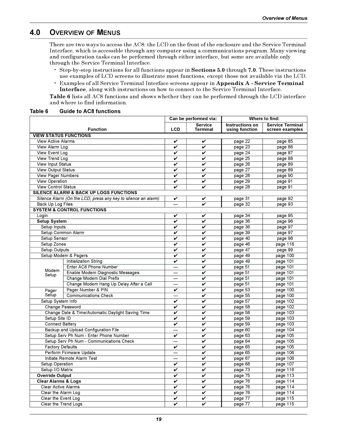
Table 6 lists all AC8 functions and shows whether they can be performed through the LCD interface and where to find information.
Table 6 | Guide to AC8 functions |
|
|
|
| ||
|
|
|
| Can be performed via: | Where to find: | ||
|
|
| Function | LCD | Service | Instructions on | Service Terminal |
|
|
| Terminal | using function | screen examples | ||
VIEW STATUS FUNCTIONS |
|
|
|
| |||
View Active Alarms | ✔ | ✔ | page 22 | page 85 | |||
View Alarm Log | ✔ | ✔ | page 23 | page 86 | |||
View Event Log | ✔ | ✔ | page 24 | page 87 | |||
View Trend Log | ✔ | ✔ | page 25 | page 88 | |||
View Input Status | ✔ | ✔ | page 26 | page 89 | |||
View Output Status | ✔ | ✔ | page 27 | page 89 | |||
View Pager Numbers | ✔ | ✔ | page 28 | page 90 | |||
View Operation | ✔ | ✔ | page 29 | page 91 | |||
View Control Status | ✔ | ✔ | page 28 | page 91 | |||
SILENCE ALARM & BACK UP LOGS FUNCTIONS |
|
|
|
| |||
Silence Alarm (On the LCD, press any key to silence an alarm) | ✔ | ✔ | page 31 | page 92 | |||
Back Up Log Files | — | ✔ | page 32 | page 93 | |||
SYSTEM & CONTROL FUNCTIONS |
|
|
|
| |||
Login |
|
|
| ✔ | ✔ | page 34 | page 95 |
Setup System |
| ✔ | ✔ | page 36 | page 96 | ||
Setup Inputs |
| ✔ | ✔ | page 36 | page 97 | ||
Setup Common Alarm | ✔ | ✔ | page 39 | page 97 | |||
Setup Sensor | ✔ | ✔ | page 40 | page 98 | |||
Setup Zones |
| ✔ | ✔ | page 46 | page 116 | ||
Setup Outputs | ✔ | ✔ | page 47 | page 99 | |||
Setup Modem & Pagers | ✔ | ✔ | page 49 | page 100 | |||
|
|
| Initialization String | ✔ | ✔ | page 49 | page 101 |
Modem |
| Enter AC8 Phone Number | — | ✔ | page 51 | page 101 | |
| Enable Modem Diagnostic Messages | — | ✔ | page 51 | page 101 | ||
Setup |
|
| |||||
|
| Change Modem Dial Prefix | — | ✔ | page 51 | page 101 | |
|
|
| |||||
|
|
| Change Modem Hang Up Delay After a Call | — | ✔ | page 51 | page 101 |
Pager |
|
| Pager Number & PIN | ✔ | ✔ | page 53 | page 100 |
Setup |
|
| Communications Check | — | ✔ | page 55 | page 100 |
Setup System Info | ✔ | ✔ | page 57 | page 102 | |||
Change Password | ✔ | ✔ | page 58 | page 102 | |||
Change Date & Time/Automatic Daylight Saving Time | ✔ | ✔ | page 58 | page 103 | |||
Setup Site ID | ✔ | ✔ | page 59 | page 103 | |||
Connect Battery | ✔ | ✔ | page 59 | page 103 | |||
Backup and Upload Configuration File | — | ✔ | page 60 | page 104 | |||
Setup Serv Ph Num - Enter Phone Number | ✔ | ✔ | page 63 | page 105 | |||
Setup Serv Ph Num - Communications Check | — | ✔ | page 64 | page 105 | |||
Factory Defaults | ✔ | ✔ | page 65 | page 105 | |||
Perform Firmware Update | — | ✔ | page 65 | page 106 | |||
Initiate Remote Alarm Test | — | ✔ | page 67 | page 106 | |||
Setup Operation | ✔ | ✔ | page 68 | page 107 | |||
Setup I/O Matrix | ✔ | ✔ | page 73 | page 116 | |||
Override Output | ✔ | ✔ | page 75 | page 113 | |||
Clear Alarms & Logs | ✔ | ✔ | page 76 | page 114 | |||
Clear Active Alarms | ✔ | ✔ | page 76 | page 114 | |||
Clear the Alarm Log | ✔ | ✔ | page 76 | page 114 | |||
Clear the Event Log | ✔ | ✔ | page 77 | page 115 | |||
Clear the Trend Logs | ✔ | ✔ | page 77 | page 115 | |||
19
