Introduction
1.7Controller Board Overview
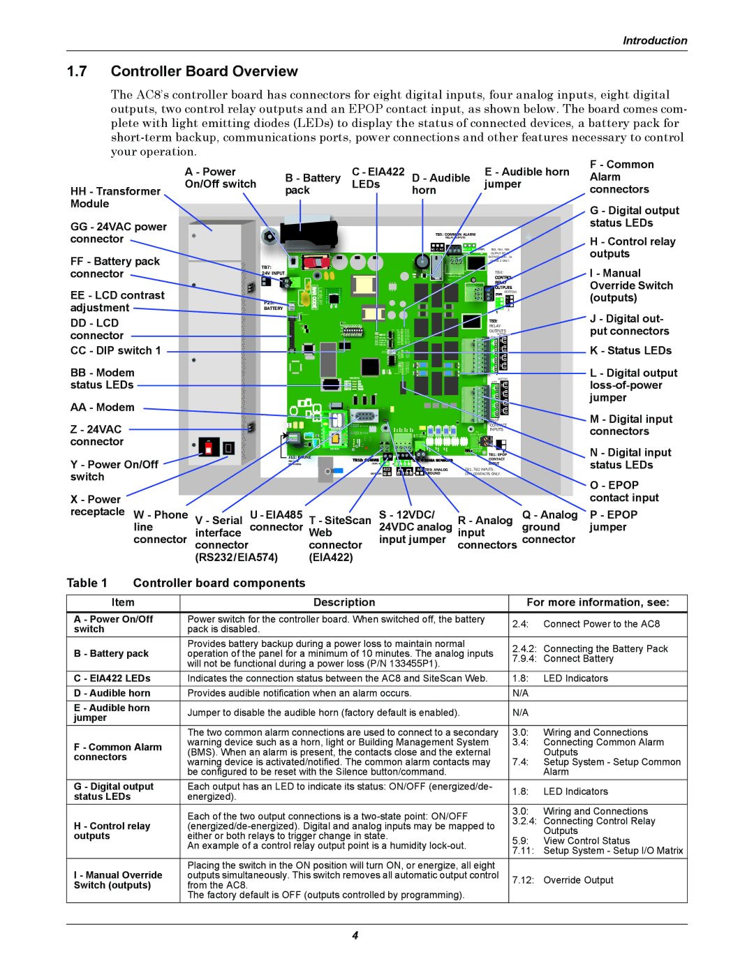
The AC8’s controller board has connectors for eight digital inputs, four analog inputs, eight digital outputs, two control relay outputs and an EPOP contact input, as shown below. The board comes com- plete with light emitting diodes (LEDs) to display the status of connected devices, a battery pack for
| A - Power | B - Battery | C - EIA422 | D - Audible | E - Audible horn | |
HH - Transformer | On/Off switch | pack | LEDs | horn | jumper | |
Module |
|
|
|
|
|
|
|
|
|
|
|
| |
GG - 24VAC power |
|
|
|
|
|
|
connector |
|
|
|
| TB5: ALARM |
|
|
|
|
|
| RELAY |
|
|
|
|
|
|
|
|
|
|
|
|
|
|
|
|
| NO C NC | NO C | TB3, TB4, TB5 |
FF - Battery pack | TB7: |
|
|
|
|
|
|
|
|
|
|
|
|
|
|
|
| OUTPUT |
|
|
|
|
|
|
|
|
|
|
|
|
|
|
|
| 3A | ||
connector |
|
|
|
|
|
|
|
|
|
|
|
|
|
| + |
|
| 2 ONLY. |
| START |
|
|
|
|
|
|
|
|
|
|
|
| Q11 |
|
|
| |
| INPUT |
|
|
|
|
|
|
|
|
|
|
|
|
| AUDIBLE |
| TOP | TB4: |
|
|
| BARCODE |
|
|
|
|
|
|
|
|
|
|
|
|
| ||
EE - LCD contrast |
| BATTERY | LIEBERT |
|
|
|
|
|
|
|
|
|
|
|
|
| NC C | |
|
|
|
|
|
|
|
|
|
|
|
|
|
|
|
|
|
| (BOTTOM) |
adjustment |
|
|
|
|
|
|
|
|
|
|
|
|
|
|
|
|
| NC |
| CONTRAST |
|
|
|
|
|
|
|
|
|
|
|
|
|
|
| C | |
| BATTERY |
|
|
|
|
|
|
|
|
|
|
|
|
|
|
|
| 2 |
DD - LCD |
| LCD |
|
|
|
|
|
|
|
|
|
|
|
|
|
|
|
|
|
|
| S2 | ON |
|
|
|
| DIP |
|
|
|
|
|
| |||
|
|
|
|
| TP1 |
|
|
|
|
|
|
|
|
|
|
|
|
|
|
| VBATT |
| ON |
|
|
|
|
|
|
|
|
|
|
|
|
| RELAY |
connector |
|
|
| GND |
|
|
|
|
|
|
|
|
|
|
|
|
|
|
|
|
|
|
|
|
|
|
|
|
| DS83 | CAN TX |
|
|
|
| 8 | |
|
|
|
|
| 1 | 2 | 3 | 4 | 5 | 6 | 7 | 8 |
|
|
|
|
| OUTPUTS |
|
|
|
| OFF |
|
|
|
|
|
|
|
|
|
|
|
|
| (BOTTOM) |
|
|
|
|
|
|
|
|
|
|
|
|
|
|
|
|
|
| (TOP) |
CC - DIP switch 1 |
|
|
|
|
|
|
|
|
|
|
| DS84 CAN RX |
|
|
|
| 4 | |
|
|
|
|
|
|
|
|
|
|
|
|
|
|
|
|
| 7 | |
|
|
|
|
|
|
|
|
|
|
|
|
|
|
|
|
|
| 3 |
|
|
|
|
|
|
|
|
|
|
|
|
|
|
|
|
|
| 6 |
|
|
|
|
|
|
|
|
|
|
|
|
|
|
|
|
|
| 2 |
BB - Modem |
|
|
|
|
|
|
|
|
|
|
|
|
|
|
| PFM2 |
| 5 |
|
|
|
|
|
|
|
|
|
|
|
|
|
|
|
|
| 1 | |
|
|
|
|
|
|
|
|
|
|
|
|
|
|
| PFM5 |
|
| |
|
|
|
|
|
| MODEM |
|
|
|
|
| REV | (BOTTOM) | |||||
status LEDs |
|
|
|
|
|
|
|
|
|
|
|
|
|
|
|
| (TOP) | |
|
|
|
|
|
|
|
|
|
|
|
|
|
|
|
|
| 4 | |
|
|
|
|
|
|
|
|
|
|
|
|
|
|
|
|
|
| 8 |
|
|
|
|
|
|
|
|
|
|
|
|
|
|
|
|
|
| 7 |
AA - Modem |
|
|
|
|
|
|
|
|
|
|
|
|
|
|
|
|
| 3 |
|
|
|
|
|
|
|
|
|
|
|
|
|
|
|
|
| 1 5 | |
|
|
|
|
|
|
|
|
|
|
|
|
|
|
|
|
|
| 6 |
|
|
|
|
|
|
|
|
|
|
|
|
|
|
|
|
|
| 2 |
Z - 24VAC |
|
|
|
|
|
|
|
|
|
|
|
|
|
|
| EPOP INPUT |
| |
|
|
|
|
|
|
|
|
|
|
|
|
|
|
|
|
| ASS | INPUTS |
|
|
|
|
|
|
|
|
|
|
|
|
|
|
|
|
| TB1 | |
connector |
|
|
|
|
|
|
|
|
|
|
|
|
|
|
|
|
| |
|
|
| MODEM |
|
|
|
|
|
|
|
|
|
|
|
| P19 |
| |
| ON |
|
|
|
|
|
|
|
|
|
|
|
|
|
|
| EPOP |
|
|
|
|
|
|
|
|
|
|
|
|
|
|
|
|
|
| EPOP |
|
|
|
|
|
|
|
|
|
|
|
|
|
|
|
|
|
| DIS EN | TB1: EPOP |
Y - Power On/Off |
| J11: |
|
|
|
|
|
|
|
|
|
|
|
|
|
|
| CONTACT |
| PIN |
|
|
|
|
|
|
|
|
|
| 422 |
| AG | ANALOG |
| ||
|
|
|
|
|
|
|
|
|
|
|
| TB2 INPUTS: | ||||||
switch |
|
|
|
|
|
|
|
|
|
| (TOP) | — | + | + — |
|
|
| |
|
|
|
|
|
|
|
|
|
|
|
| + — | + | + — |
|
| ONLY. | |
X - Power |
|
|
|
|
|
| |
receptacle W - Phone | V - Serial | U - EIA485 | T - SiteScan | S - 12VDC/ | R - Analog | Q - Analog | |
line | connector | 24VDC analog | ground | ||||
interface | Web | input | |||||
connector | connector |
| connector | input jumper | connectors | connector | |
| (RS232/EIA574) | (EIA422) |
|
|
| ||
F - Common Alarm connectors
G - Digital output status LEDs
H - Control relay outputs
I - Manual Override Switch (outputs)
J - Digital out- put connectors
K - Status LEDs
L - Digital output
M - Digital input connectors
N - Digital input status LEDs
O - EPOP contact input
P - EPOP jumper
Table 1 | Controller board components |
|
| ||
|
|
| |||
Item | Description | For more information, see: | |||
A - Power On/Off | Power switch for the controller board. When switched off, the battery | 2.4: | Connect Power to the AC8 | ||
switch |
| pack is disabled. | |||
|
|
| |||
|
| Provides battery backup during a power loss to maintain normal | 2.4.2: Connecting the Battery Pack | ||
B - Battery pack | operation of the panel for a minimum of 10 minutes. The analog inputs | ||||
7.9.4: Connect Battery | |||||
|
| will not be functional during a power loss (P/N 133455P1). | |||
|
|
|
| ||
C - EIA422 LEDs | Indicates the connection status between the AC8 and SiteScan Web. | 1.8: | LED Indicators | ||
D - Audible horn | Provides audible notification when an alarm occurs. | N/A |
| ||
E - Audible horn | Jumper to disable the audible horn (factory default is enabled). | N/A |
| ||
jumper |
|
| |||
|
|
|
| ||
|
| The two common alarm connections are used to connect to a secondary | 3.0: | Wiring and Connections | |
F - Common Alarm | warning device such as a horn, light or Building Management System | 3.4: | Connecting Common Alarm | ||
(BMS). When an alarm is present, the contacts close and the external |
| Outputs | |||
connectors |
| 7.4: | |||
| warning device is activated/notified. The common alarm contacts may | Setup System - Setup Common | |||
|
| be configured to be reset with the Silence button/command. |
| Alarm | |
G - Digital output | Each output has an LED to indicate its status: ON/OFF (energized/de- | 1.8: | LED Indicators | ||
status LEDs |
| energized). | |||
|
|
| |||
|
| Each of the two output connections is a | 3.0: | Wiring and Connections | |
|
| 3.2.4: Connecting Control Relay | |||
H - Control relay | |||||
| Outputs | ||||
outputs |
| either or both relays to trigger change in state. |
| ||
| 5.9: | View Control Status | |||
|
| An example of a control relay output point is a humidity | |||
|
| 7.11: Setup System - Setup I/O Matrix | |||
|
|
| |||
I - Manual Override | Placing the switch in the ON position will turn ON, or energize, all eight |
|
| ||
outputs simultaneously. This switch removes all automatic output control | 7.12: | Override Output | |||
Switch (outputs) | from the AC8. | ||||
|
| ||||
|
| The factory default is OFF (outputs controlled by programming). |
|
| |
4