Wiring and Connections
3.4Connecting Common Alarm Outputs
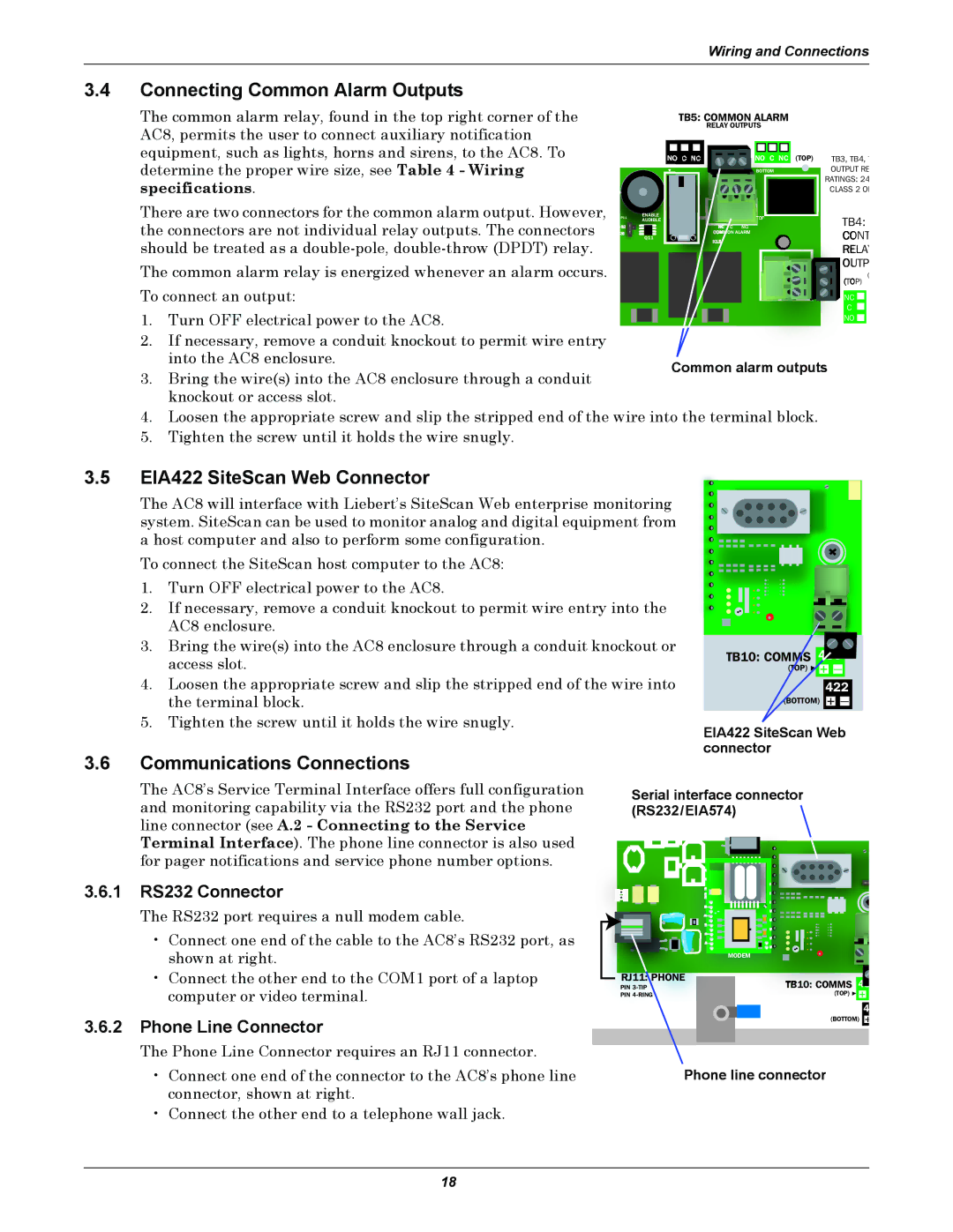
The common alarm relay, found in the top right corner of the AC8, permits the user to connect auxiliary notification
TB5: COMMON ALARM
RELAY OUTPUTS
equipment, such as lights, horns and sirens, to the AC8. To determine the proper wire size, see Table 4 - Wiring specifications.
There are two connectors for the common alarm output. However, the connectors are not individual relay outputs. The connectors should be treated as a
The common alarm relay is energized whenever an alarm occurs.
+
P11
40
2
ENABLE AUDIBLE
Q11
|
|
|
|
|
| (TOP) |
NO |
| C NC | NO C NC | |||
![]() BOTTOM
BOTTOM
TOP
CNO ON ALARM
TB3, TB4,
OUTPUT RE RATINGS: 24 CLASS 2 ON
TB4:
![]()
![]() ONT
ONT ![]() ELA
ELA
![]() UTP
UTP
![]() P)
P)
(
To connect an output:
1.Turn OFF electrical power to the AC8.
2.If necessary, remove a conduit knockout to permit wire entry into the AC8 enclosure.
3.Bring the wire(s) into the AC8 enclosure through a conduit knockout or access slot.
![]()
![]() NC
NC ![]()
C
NO ![]()
Common alarm outputs
4.Loosen the appropriate screw and slip the stripped end of the wire into the terminal block.
5.Tighten the screw until it holds the wire snugly.
3.5EIA422 SiteScan Web Connector
The AC8 will interface with Liebert’s SiteScan Web enterprise monitoring system. SiteScan can be used to monitor analog and digital equipment from a host computer and also to perform some configuration.
To connect the SiteScan host computer to the AC8:
1.Turn OFF electrical power to the AC8.
2.If necessary, remove a conduit knockout to permit wire entry into the AC8 enclosure.
3.Bring the wire(s) into the AC8 enclosure through a conduit knockout or access slot.
4.Loosen the appropriate screw and slip the stripped end of the wire into the terminal block.
5.Tighten the screw until it holds the wire snugly.
3.6Communications Connections
TB10: CO S 485
![]() + —
+ —
422
+ —
EIA422 SiteScan Web connector
The AC8’s Service Terminal Interface offers full configuration and monitoring capability via the RS232 port and the phone line connector (see A.2 - Connecting to the Service Terminal Interface). The phone line connector is also used for pager notifications and service phone number options.
3.6.1RS232 Connector
The RS232 port requires a null modem cable.
•Connect one end of the cable to the AC8’s RS232 port, as shown at right.
•Connect the other end to the COM1 port of a laptop computer or video terminal.
3.6.2Phone Line Connector
The Phone Line Connector requires an RJ11 connector.
•Connect one end of the connector to the AC8’s phone line connector, shown at right.
•Connect the other end to a telephone wall jack.
Serial interface connector (RS232/EIA574)
MODEM |
PHONE
PIN | TB10: COMMS | |
PIN | (TOP) | + |
4
(BOTTOM) +
Phone line connector
18