Wiring and Connections
3.2Connecting Digital Inputs and Digital Outputs
The digital inputs, digital outputs and control relay outputs are found on the right side of the AC8’s printed wiring assembly board. Each set has two terminal
•Digital inputs: two terminal blocks, with four inputs per block (8 inputs total)
•Digital outputs: two terminal blocks, with four outputs per block (8 outputs total)
•Control relay outputs: two terminal blocks, with one output per block (2 outputs total)
Each input is tied to an output with the same number:
•Input 1 is tied to Output 1 (default name: Device_1)
•Input 2 is tied to Output 2 (default name: Device_2)
•Input 3 is tied to Output 3 (default name: Device_3)
...
• Input 8 is tied to Output 8 (default name: Device_8)
Up to eight devices may be connected to the AC8. Each device must be connected to an input and an output with the same number.
To determine the proper wire size, see Table 4 - Wiring specifications.
NOTE
Each terminal block is a removable,
After making the connections, push the removed piece back into the portion attached to the printed wiring assembly until the terminal block pieces lock together.
Connecting Liebert Environmental Units
For Liebert environmental units, follow these steps (be sure to connect the same device to inputs and outputs with the same
•Connect a digital input from the AC8 to the Common Alarm Relay of the environmental unit: terminals 75/76 or
•Connect a digital output (numbered the same as the input) from the AC8 to the Remote Shutdown (Power Control) of the environmental unit: terminal 37/38 or
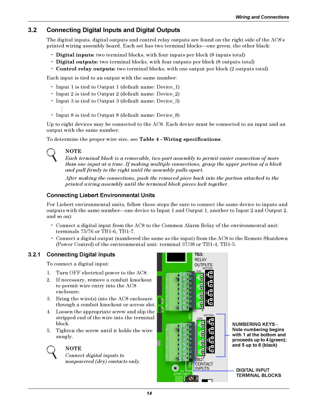
3.2.1Connecting Digital Inputs
To connect a digital input:
1.Turn OFF electrical power to the AC8.
2.If necessary, remove a conduit knockout to permit wire entry into the AC8 enclosure.
3.Bring the wire(s) into the AC8 enclosure through a conduit knockout or access slot.
4.Loosen the appropriate screw and slip the stripped end of the wire into the terminal block.
5.Tighten the screw until it holds the wire snugly.
NOTE
Connect digital inputs to nonpowered (dry) contacts only.
|
| RELAY | |
|
| OUTPUTS | |
|
| (BOTTOM) | |
|
| (TOP) | |
|
| 8 | |
|
| 4 | |
|
| 7 | |
|
| 3 | |
|
| 6 | |
ON OFF |
| 2 | |
PFM2 | 5 | ||
1 | |||
ON OFF |
| ||
PFM5 |
| ||
| REV | (BOTTOM) | |
| (TOP) | ||
|
| 8 | |
|
| 4 | |
|
| 7 | |
|
| 3 | |
|
| 6 | |
|
| 2 | |
|
| 5 | |
|
| 1 | |
| ASS | TB2: | |
| CONTACT | ||
| INPUTS | ||
| TB1 | ||
|
|
EPOP INPUT
EPOP |
NUMBERING KEYS - Note numbering begins with 1 at the bottom and proceeds up to 4 (green); and 5 up to 8 (black)
DIGITAL INPUT TERMINAL BLOCKS
14