Wiring and Connections
3.3Connecting Analog Inputs
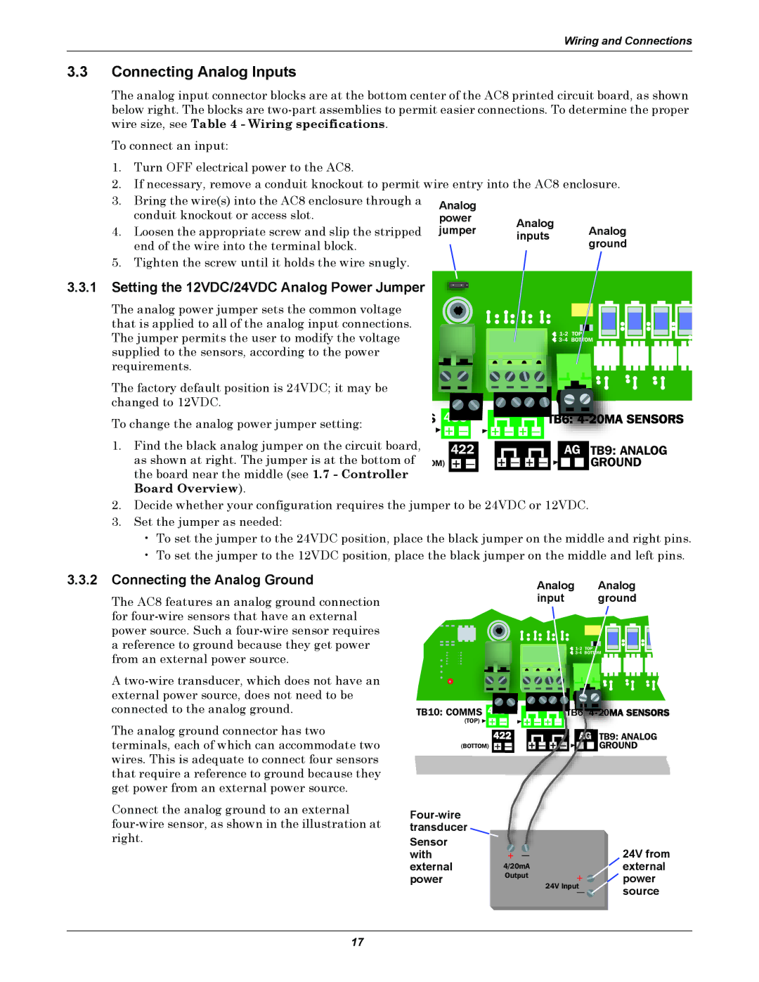
The analog input connector blocks are at the bottom center of the AC8 printed circuit board, as shown below right. The blocks are
To connect an input:
1.Turn OFF electrical power to the AC8.
2.If necessary, remove a conduit knockout to permit wire entry into the AC8 enclosure.
3.Bring the wire(s) into the AC8 enclosure through a conduit knockout or access slot.
4.Loosen the appropriate screw and slip the stripped end of the wire into the terminal block.
5.Tighten the screw until it holds the wire snugly.
Analog
power Analog
jumper inputs Analog ground
3.3.1Setting the 12VDC/24VDC Analog Power Jumper
The analog power jumper sets the common voltage that is applied to all of the analog input connections. The jumper permits the user to modify the voltage supplied to the sensors, according to the power requirements.
The factory default position is 24VDC; it may be changed to 12VDC.
To change the analog power jumper setting:
1.Find the black analog jumper on the circuit board, as shown at right. The jumper is at the bottom of the board near the middle (see 1.7 - Controller Board Overview).
S |
|
|
|
|
|
|
|
|
|
|
|
|
|
|
|
|
|
|
|
|
|
|
|
|
|
|
|
|
|
|
|
|
|
|
|
|
|
|
|
|
|
|
|
|
|
|
|
|
|
|
|
|
|
|
|
|
|
|
|
|
|
| |
| + |
| — |
|
| + |
| — |
| + |
| — |
|
|
|
|
|
|
|
|
|
| |||||||||
|
|
|
|
|
|
|
|
|
|
|
|
|
|
|
|
|
|
|
|
|
|
|
|
|
|
|
|
|
|
|
|
|
| 422 |
|
|
|
|
|
|
|
|
|
|
|
|
|
|
|
|
| AG | TB9: ANALOG | ||||||||||
OM) | + |
| — |
|
| + |
| — |
| + |
| — |
|
|
|
|
|
|
|
| GROUND | ||||||||||
2.Decide whether your configuration requires the jumper to be 24VDC or 12VDC.
3.Set the jumper as needed:
•To set the jumper to the 24VDC position, place the black jumper on the middle and right pins.
•To set the jumper to the 12VDC position, place the black jumper on the middle and left pins.
3.3.2Connecting the Analog Ground
The AC8 features an analog ground connection for
A
The analog ground connector has two terminals, each of which can accommodate two wires. This is adequate to connect four sensors that require a reference to ground because they get power from an external power source.
Connect the analog ground to an external
Analog Analog
input ground
TB10: COMMS ![]()
![]()
(TOP)![]() +
+ ![]()
|
|
| TB9: ANALOG |
|
|
| |
|
| GROUND | |
(BOTTOM) | + |
| |
Sensor |
|
| 24V from |
with | + — |
| |
external | 4/20mA |
| external |
power | Output | + | power |
|
| ||
|
|
| |
|
| 24V Input | source |
|
| — |
17