Monitor: Basic Operation
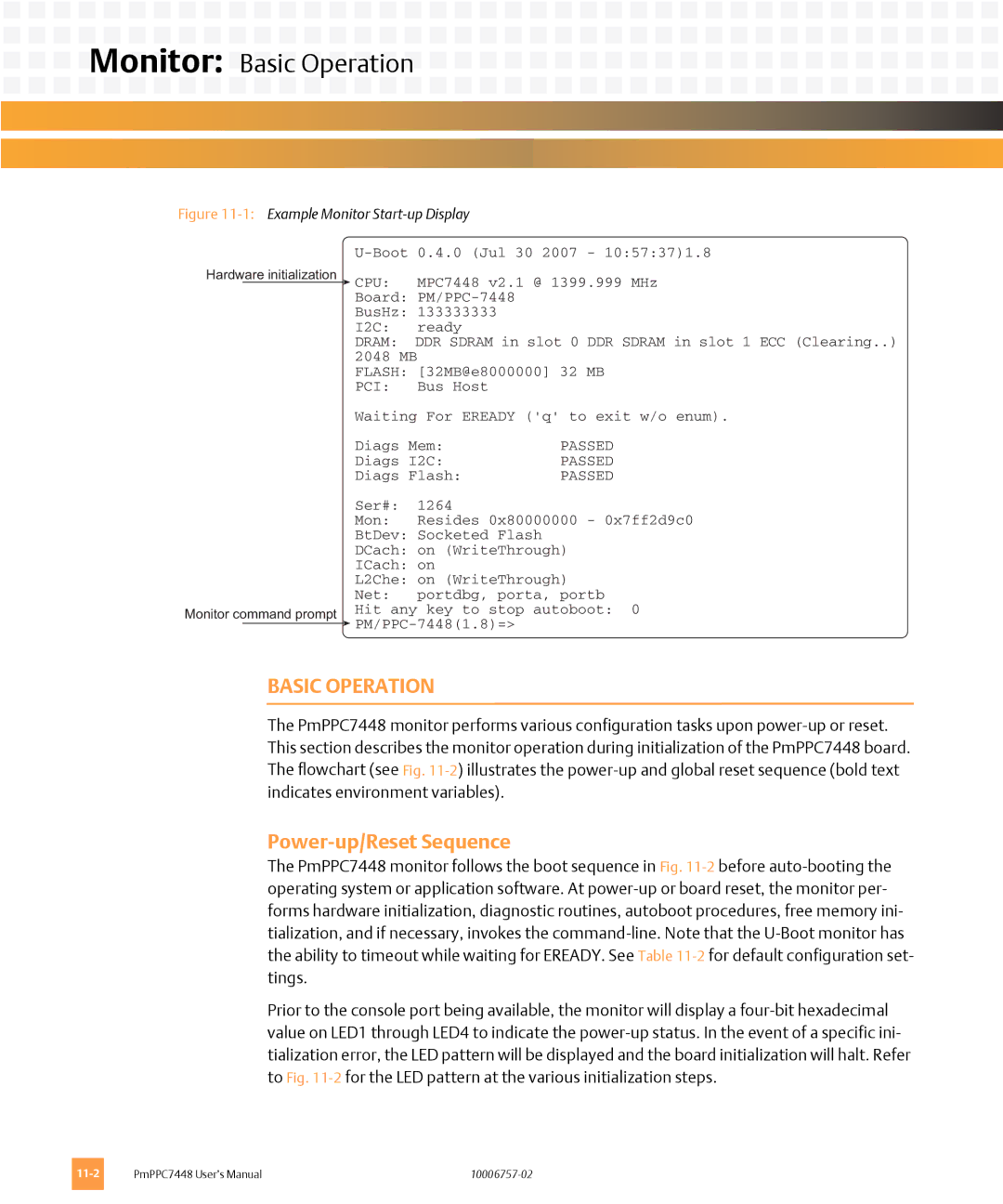
Figure 11-1: Example Monitor Start-up Display
|
| 0.4.0 (Jul 30 2007 - 10:57:37)1.8 | ||
Hardware initialization | CPU: | MPC7448 v2.1 @ 1399.999 MHz | ||
|
| |||
|
| Board: |
| |
|
| BusHz: | 133333333 |
|
|
| I2C: | ready |
|
|
| DRAM: DDR SDRAM in slot 0 DDR SDRAM in slot 1 ECC (Clearing..) | ||
|
| 2048 MB |
|
|
|
| FLASH: [32MB@e8000000] 32 MB | ||
|
| PCI: | Bus Host |
|
|
| Waiting For EREADY ('q' to exit w/o enum). | ||
|
| Diags Mem: | PASSED | |
|
| Diags I2C: | PASSED | |
|
| Diags Flash: | PASSED | |
|
| Ser#: | 1264 |
|
|
| Mon: | Resides 0x80000000 - 0x7ff2d9c0 | |
|
| BtDev: | Socketed Flash |
|
|
| DCach: | on (WriteThrough) | |
|
| ICach: | on |
|
|
| L2Che: | on (WriteThrough) | |
|
| Net: | portdbg, porta, portb | |
Monitor command prompt | Hit any key to stop autoboot: 0 | ||
|
| ||
BASIC OPERATION
The PmPPC7448 monitor performs various configuration tasks upon
Power-up/Reset Sequence
The PmPPC7448 monitor follows the boot sequence in Fig.
Prior to the console port being available, the monitor will display a
PmPPC7448 User’s Manual |