Ethernet Interface: Ethernet Connection (P1)


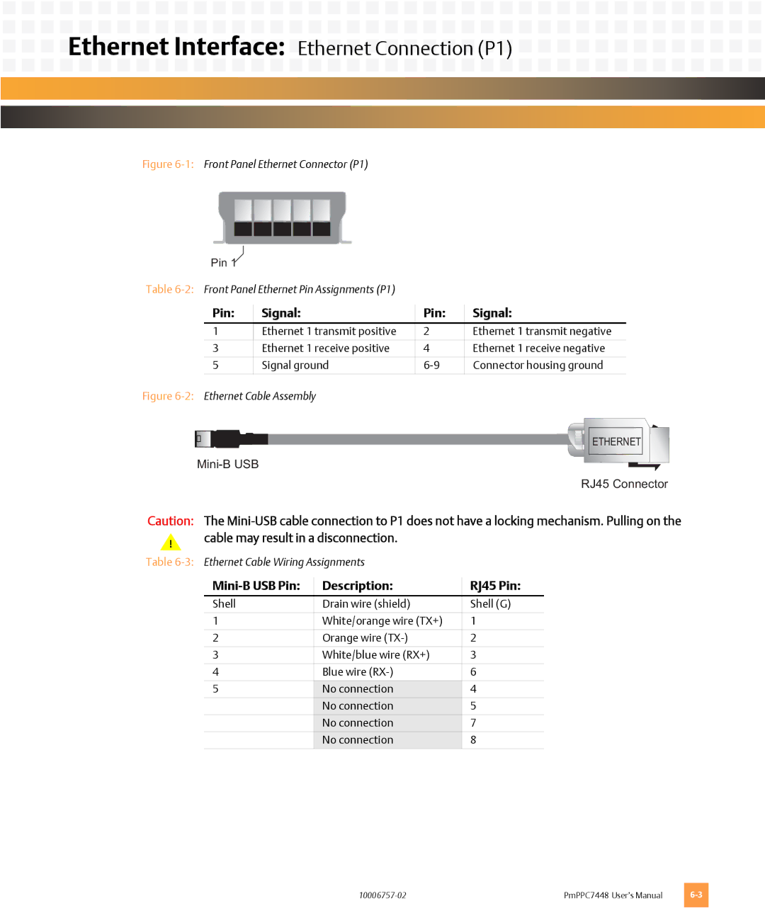
Figure 6-1: Front Panel Ethernet Connector (P1)
Pin 1
Table
Pin: | Signal: | Pin: | Signal: |
1 | Ethernet 1 transmit positive | 2 | Ethernet 1 transmit negative |
|
|
|
|
3 | Ethernet 1 receive positive | 4 | Ethernet 1 receive negative |
|
|
|
|
5 | Signal ground | Connector housing ground | |
|
|
|
|
Figure 6-2: Ethernet Cable Assembly
![]()
![]()
![]()
![]()
![]()
![]()
![]()
![]() ETHERNET
ETHERNET
RJ45 Connector
Caution: The
!cable may result in a disconnection.
Table
| Description: | RJ45 Pin: |
Shell | Drain wire (shield) | Shell (G) |
|
|
|
1 | White/orange wire (TX+) | 1 |
|
|
|
2 | Orange wire | 2 |
|
|
|
3 | White/blue wire (RX+) | 3 |
|
|
|
4 | Blue wire | 6 |
|
|
|
5 | No connection | 4 |
| No connection | 5 |
| No connection | 7 |
| No connection | 8 |
|
|
|
PmPPC7448 User’s Manual |