Emerson PMPPC7448 On-CardMemory Configuration, Boot Memory Configuration, User Flash, Jumper

Models: PMPPC7448

1 136
Download 136 pages 56.22 Kb
Page 51
Image 51
On-Card Memory Configuration

BOOT MEMORY CONFIGURATIONJumper:Function:Options:Default Configuration:USER FLASHDeviceData Path Section 4Total Memory

Density:No. of Banks:(Megabytes):Manual backgroundOn-Card Memory Configuration Manual backgroundManual backgroundManual backgroundManual background

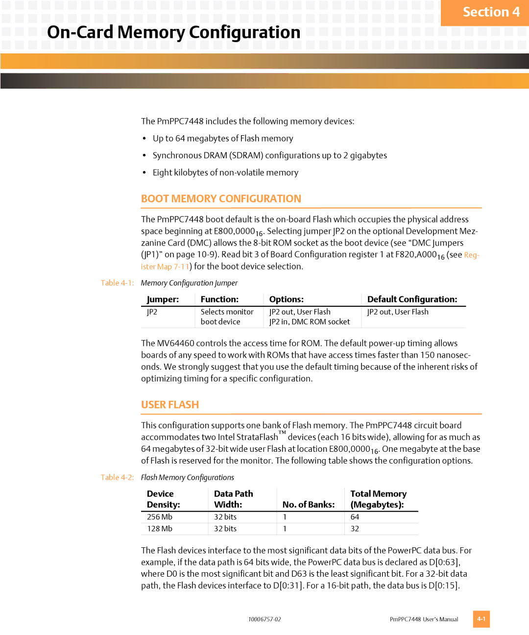
The PmPPC7448 includes the following memory devices:

Up to 64 megabytes of Flash memory

Synchronous DRAM (SDRAM) configurations up to 2 gigabytes

Eight kilobytes of non-volatile memory

BOOT MEMORY CONFIGURATION

The PmPPC7448 boot default is the on-board Flash which occupies the physical address space beginning at E800,000016. Selecting jumper JP2 on the optional Development Mez- zanine Card (DMC) allows the 8-bit ROM socket as the boot device (see “DMC Jumpers (JP1)” on page 10-9). Read bit 3 of Board Configuration register 1 at F820,A00016 (see Reg- ister Map 7-11) for the boot device selection.

Table 4-1:Memory Configuration Jumper

Jumper:

Function:

Options:

Default Configuration:

JP2

Selects monitor

JP2 out, User Flash

JP2 out, User Flash


boot device

JP2 in, DMC ROM socket


The MV64460 controls the access time for ROM. The default power-up timing allows boards of any speed to work with ROMs that have access times faster than 150 nanosec- onds. We strongly suggest that you use the default timing because of the inherent risks of optimizing timing for a specific configuration.

USER FLASH

This configuration supports one bank of Flash memory. The PmPPC7448 circuit board accommodates two Intel StrataFlashdevices (each 16 bits wide), allowing for as much as 64 megabytes of 32-bit wide user Flash at location E800,000016. One megabyte at the base of Flash is reserved for the monitor. The following table shows the configuration options.

Table 4-2:Flash Memory Configurations

Device

Data Path


Total Memory

Density:

Width:

No. of Banks:

(Megabytes):

256 Mb

32 bits

1

64


128 Mb

32 bits

1

32


The Flash devices interface to the most significant data bits of the PowerPC data bus. For example, if the data path is 64 bits wide, the PowerPC data bus is declared as D[0:63], where D0 is the most significant bit and D63 is the least significant bit. For a 32-bit data path, the Flash devices interface to D[0:31]. For a 16-bit path, the data bus is D[0:15].

10006757-02

PmPPC7448 User’s Manual

4-1

Page 51
Image 51
Emerson PMPPC7448 On-CardMemory Configuration, Boot Memory Configuration, User Flash, Jumper, Function, Options, Device