

 Overview: Functional Overview
FUNCTIONAL OVERVIEW
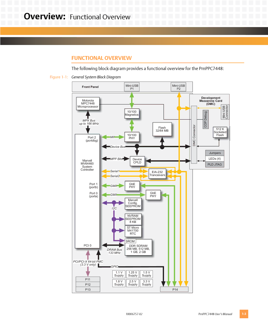
The following block diagram provides a functional overview for the PmPPC7448:
Figure 1-1: General System Block Diagram
Front Panel |
|
| ||
P1 |
| P2 |
| |
|
|
| ||
|
|
|
|
|
Motorola
MPC7448
Microprocessor
MPX Bus
up to 166 MHz
Port 2
(portdbg)
Marvell
MV64460
System
Controller
Port 1 (portb)
Port 0 (porta)
PCI 0
10/100
Magnetics
Flash
32/64 MB
MII 10/100
PHY
Device Bus
MPP Bits | Device | |||||||||
Serial1 | CPLD |
|
| |||||||
|
|
|
|
| ||||||
|
|
|
|
| ||||||
|
|
|
|
| ||||||
|
|
|
|
|
|
|
| Tranceivers | ||
Serial2 |
|
|
| |||||||
|
|
|
|
|
|
|
| |||
|
|
|
|
|
|
|
| |||
GMII |
|
| GbE | |||||||
|
| PHY | ||||||||
|
|
|
|
| ||||||
GMII |
|
|
| GbE | ||||||
|
|
| PHY | |||||||
|
|
|
|
|
|
|
| |||
|
|
|
|
| Marvell | |||||
|
|
|
|
| Config. | |||||
|
|
|
|
| ||||||
I2C | SEEPROM | |||||||||
|
|
|
|
|
| |||||
|
|
|
|
| NVRAM | |||||
|
|
|
|
| SEEPROM | |||||
|
|
|
|
| 8 KB | |||||
|
|
|
|
| ST Micro | |||||
|
|
|
|
| M41T00 | |||||
|
|
|
|
| ||||||
|
|
|
|
| RTC | |||||
|
|
|
|
|
|
|
|
|
|
|
|
|
|
|
| SROM |
|
|
|
|
|
|
|
|
|
| DDR SDRAM | |||||
|
|
|
|
| ||||||
DRAM Bus | 256 MB, 512 MB, | |||||||||
133 MHz | 1 GB, 2 GB | |||||||||
DMC Connector
Development
Mezzanine Card
(DMC)
|
|
|
|
| Mini USB Connector |
|
|
|
|
| |
|
| Debug | |||
|
|
|
|
| |
|
| COP | 512 K | ||
|
|
| |||
|
|
| Socketed | ||
|
|
| Flash | ||
Jumpers |
LEDs (4) |
PLD JTAG
|
| ||||
| (3.3 V | only) | GPIO | ||
|
|
|
| ||
|
|
|
|
|
|
|
|
|
|
| 1.1 V |
|
|
|
|
| Supply |
| P11 |
|
|
| |
|
|
|
|
| 1.8 V |
| P12 |
|
| Supply | |
| P13 |
|
|
| |
1.25V Supply
2.5V Supply
1.5V Supply
3.3V Supply
P14
PmPPC7448 User’s Manual |
