Real-Time


1Seconds register
2Minutes register
3Century/Hours register
4Day register
5Date register
6Month register
7Years register
8Control register
The M41T00 clock continually monitors the supply voltage (Vcc) for an out of tolerance condition. If Vcc falls below
•Terminates an access in progress
•Resets the device address counter
•Does not recognize inputs (prevents erroneous data from being written)
At
CLOCK OPERATION
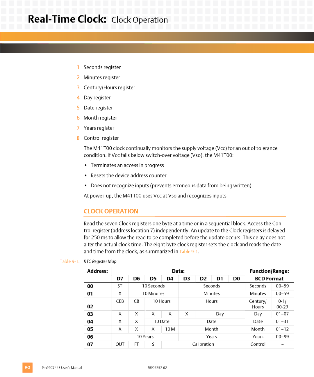
Read the seven Clock registers one byte at a time or in a sequential block. Access the Con- trol register (address location 7) independently. An update to the Clock registers is delayed for 250 ms to allow the read to be completed before the update occurs. This delay does not alter the actual clock time. The eight byte clock register sets the clock and reads the date and time from the clock, as summarized in Table
Table
Address: |
|
|
|
|
| Data: |
|
|
|
|
| Function/Range: | ||
| D7 | D6 |
| D5 |
| D4 | D3 |
| D2 |
| D1 | D0 | BCD Format | |
00 | ST |
| 10 Seconds |
|
|
| Seconds |
| Seconds | |||||
|
|
|
|
|
|
|
|
|
|
| ||||
01 | X |
| 10 Minutes |
|
|
| Minutes |
| Minutes | |||||
|
|
|
|
|
|
|
|
|
|
|
|
| ||
02 | CEB | CB |
| 10 Hours |
|
| Hours |
| Century/ | |||||
|
|
|
|
|
|
|
|
|
|
|
| Hours | ||
|
|
|
|
|
|
|
|
|
|
|
|
|
| |
03 | X | X |
| X |
| X | X |
|
|
| Day |
| Day | |
|
|
|
|
|
|
|
|
|
|
|
|
|
| |
04 | X | X |
| 10 Date |
|
|
| Date |
| Date | ||||
|
|
|
|
|
|
|
|
|
|
|
|
| ||
05 | X | X |
| X |
| 10 M |
|
| Month |
| Month | |||
|
|
|
|
|
|
|
|
|
|
|
|
| ||
06 |
| 10 Years |
|
|
| Years |
| Years | ||||||
|
|
|
|
|
|
|
|
|
|
|
|
|
| |
07 | OUT | FT |
| S |
|
|
| Calibration |
| Control | — | |||
|
|
|
|
|
|
|
|
|
|
|
|
|
|
|
PmPPC7448 User’s Manual |