PCI Reset Out Enable Register (ROER)
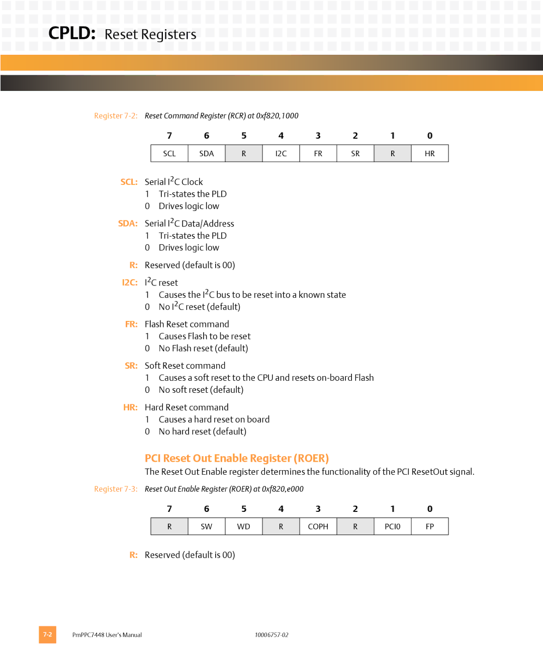
The Reset Out Enable register determines the functionality of the PCI ResetOut signal.


 CPLD:
CPLD: Reset Registers
Register
7 | 6 | 5 | 4 | 3 | 2 | 1 | 0 |
SCL
SDA
R
I2C
FR
SR
R
HR
SCL: | Serial I2C Clock | |
| 1 | |
| 0 | Drives logic low |
SDA: Serial I2C Data/Address | ||
| 1 | |
| 0 | Drives logic low |
R: | Reserved (default is 00) | |
I2C: | I2C reset | |
| 1 | Causes the I2C bus to be reset into a known state |
| 0 | No I2C reset (default) |
FR: | Flash Reset command | |
| 1 | Causes Flash to be reset |
| 0 | No Flash reset (default) |
SR: | Soft Reset command | |
| 1 | Causes a soft reset to the CPU and resets |
| 0 | No soft reset (default) |
HR: Hard Reset command | ||
| 1 | Causes a hard reset on board |
| 0 | No hard reset (default) |
Register
7 | 6 | 5 | 4 | 3 | 2 | 1 | 0 |
R
SW
WD
R
COPH
R
PCI0
FP
R:Reserved (default is 00)
PmPPC7448 User’s Manual |
