Serial Input/Output: I/O Connection


Table
Pin: | Signal: | Pin: | Signal: |
|
| 21 |
|
1 | Not connected | Receive (Rx) Data Input, | |
31 |
|
| |
Transmit (Tx) Data Output, | 4 | Not connected | |
|
|
| |
5 | Ground | Connector housing ground | |
|
|
|
|
1.Signals (pins 2 and 3) can be switched as a factory build option.
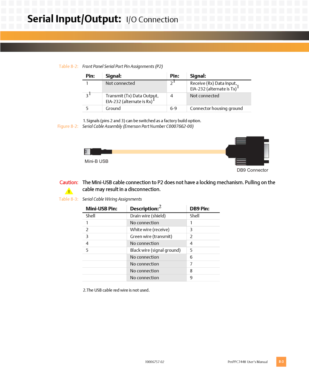
Figure 8-2: Serial Cable Assembly (Emerson Part Number C0007662-00)
DB9 Connector
Caution: The
!cable may result in a disconnection.
Table
| Description:2 | DB9 Pin: |
Shell | Drain wire (shield) | Shell |
|
|
|
1 | No connection | 1 |
2 | White wire (receive) | 3 |
|
|
|
3 | Green wire (transmit) | 2 |
|
|
|
4 | No connection | 4 |
5 | Black wire (signal ground) | 5 |
|
|
|
| No connection | 6 |
| No connection | 7 |
| No connection | 8 |
| No connection | 9 |
|
|
|
2.The USB cable red wire is not used.
PmPPC7448 User’s Manual |