Setup: Troubleshooting
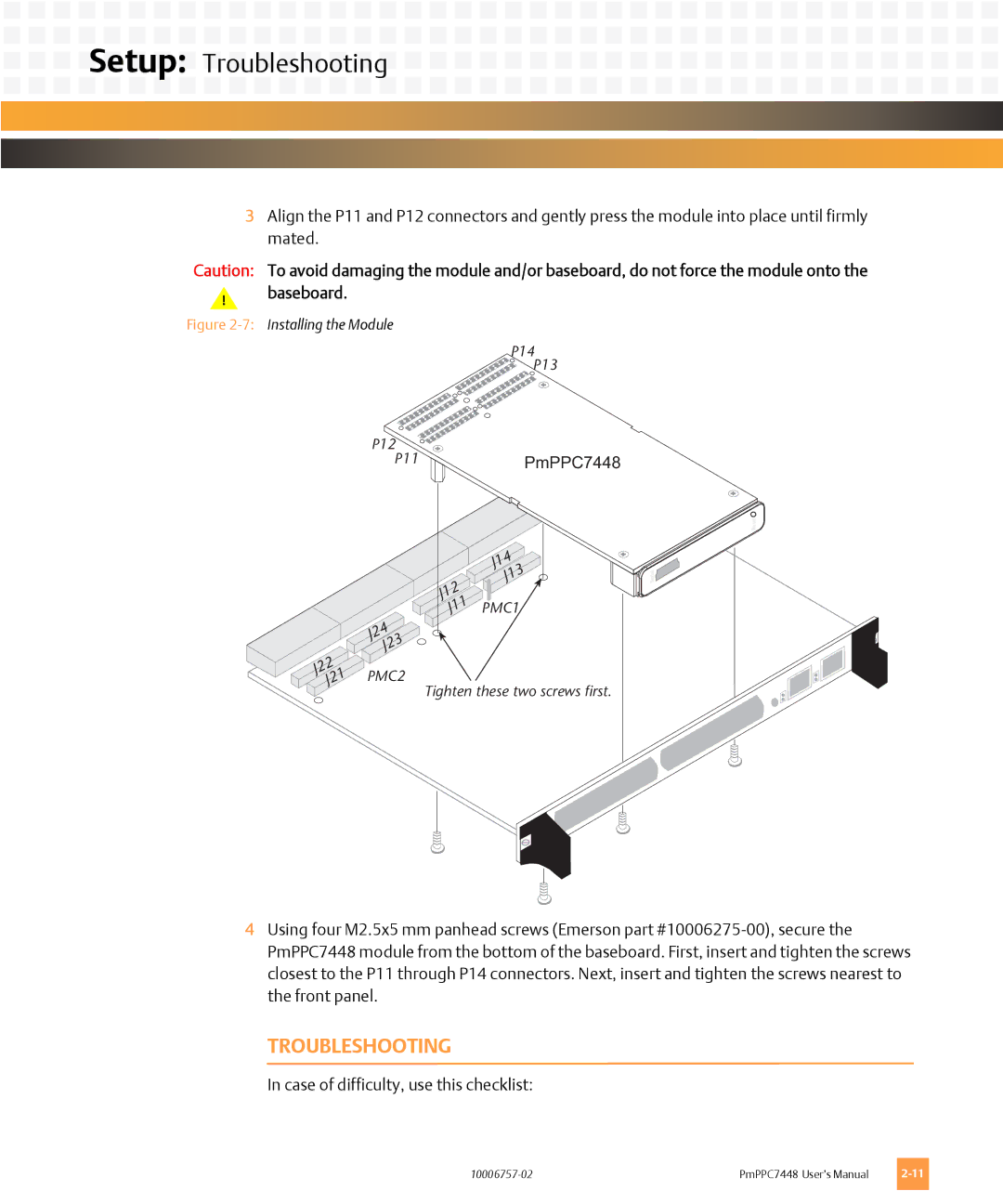
3Align the P11 and P12 connectors and gently press the module into place until firmly mated.
Caution: To avoid damaging the module and/or baseboard, do not force the module onto the
!baseboard.
Figure 2-7: Installing the Module
P14P13
P12P11 | PmPPC7448 |
J22 J21
Reset![]()
| J14 |
|
| J13 | Serial |
J12 | PMC1 |
|
J11 |
|
J24
J23
PMC2
Tighten these two screws first.
4Using four M2.5x5 mm panhead screws (Emerson part
TROUBLESHOOTING
In case of difficulty, use this checklist:
PmPPC7448 User’s Manual |